System-level hardware and software development and co-simulation system

a hardware and software development and co-simulation system technology, applied in the field of tools for developing electronic system designs, can solve the problems of little support provided for establishing the mechanisms for controlling the simulation of both parts of the system, and the present tools provide little assistance in the overall design flow of both software and hardware components of the system

Active Publication Date: 2013-06-25
XILINX INC
View PDF6 Cites 16 Cited by
  • Summary
  • Abstract
  • Description
  • Claims
  • Application Information

AI Technical Summary

Benefits of technology

[0009]An article of manufacture is provided in another embodiment. The article of manufacture comprises a processor-readable medium configured with instructions that are executable by one or more processors for co-simulating an electronic system design by performing the steps including, instantiating a hardware design function block in the design in response to user input; establishing in response to user input, a specification of a software execution platform including external ports and software to execute on the platform; automatically instantiating a software execution platform interface block in response to a user instruction to import the software execution platform into the design, the software execution platform interface block having ports compatible with the external ports of the software execution platform; generating a first simulation model from the hardware design function block and the software execution platform interface block and a second simulation model from the software execution platform; co-simulating the first and second simulation models; and communicating data between the first simulation model and the second simulation model via the interface block.

Problems solved by technology

However, present tools provide little assistance in the overall design flow for both software and hardware components of the system.
However, little support is provided for establishing the mechanisms for controlling the simulation of both parts of the system.

Method used


Image

  • System-level hardware and software development and co-simulation system
  • System-level hardware and software development and co-simulation system
  • System-level hardware and software development and co-simulation system

Examples


Embodiment Construction

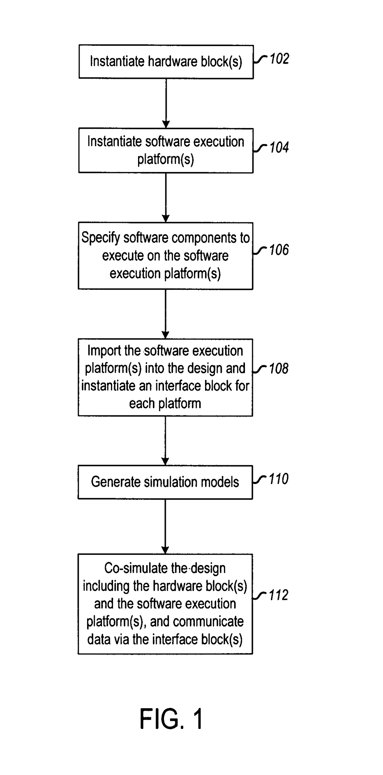
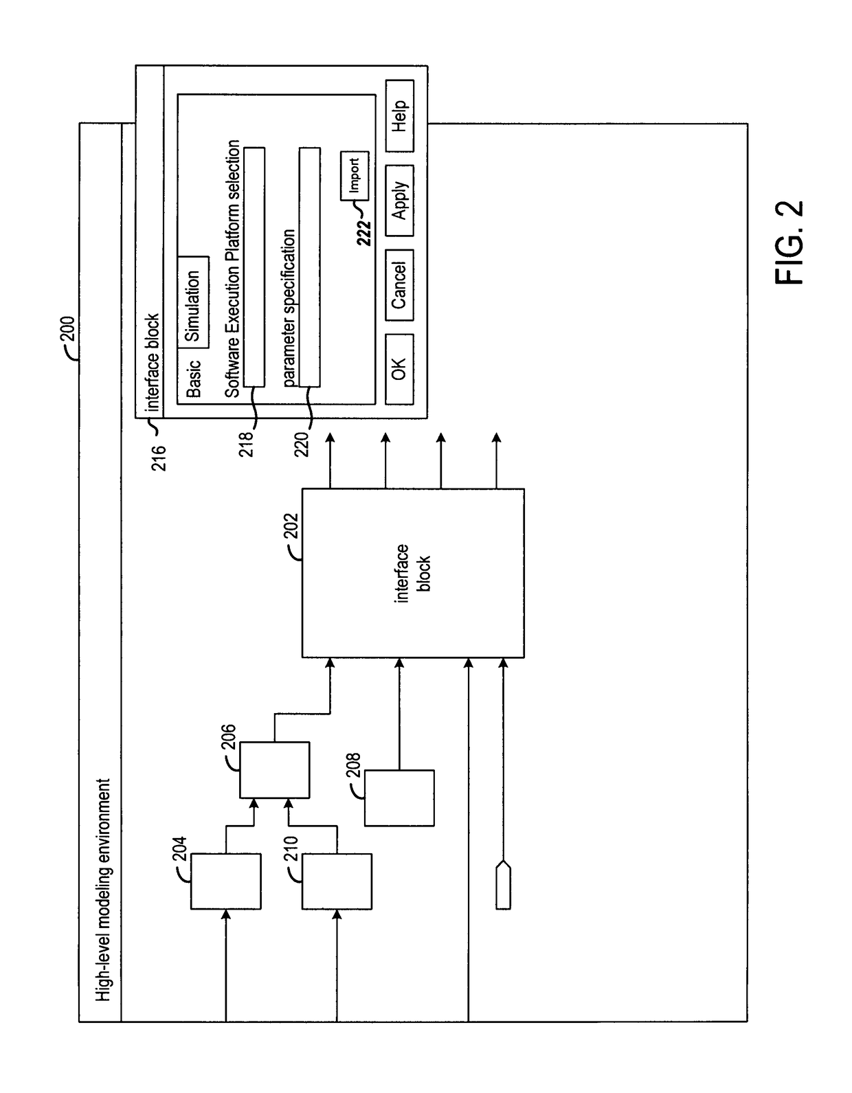
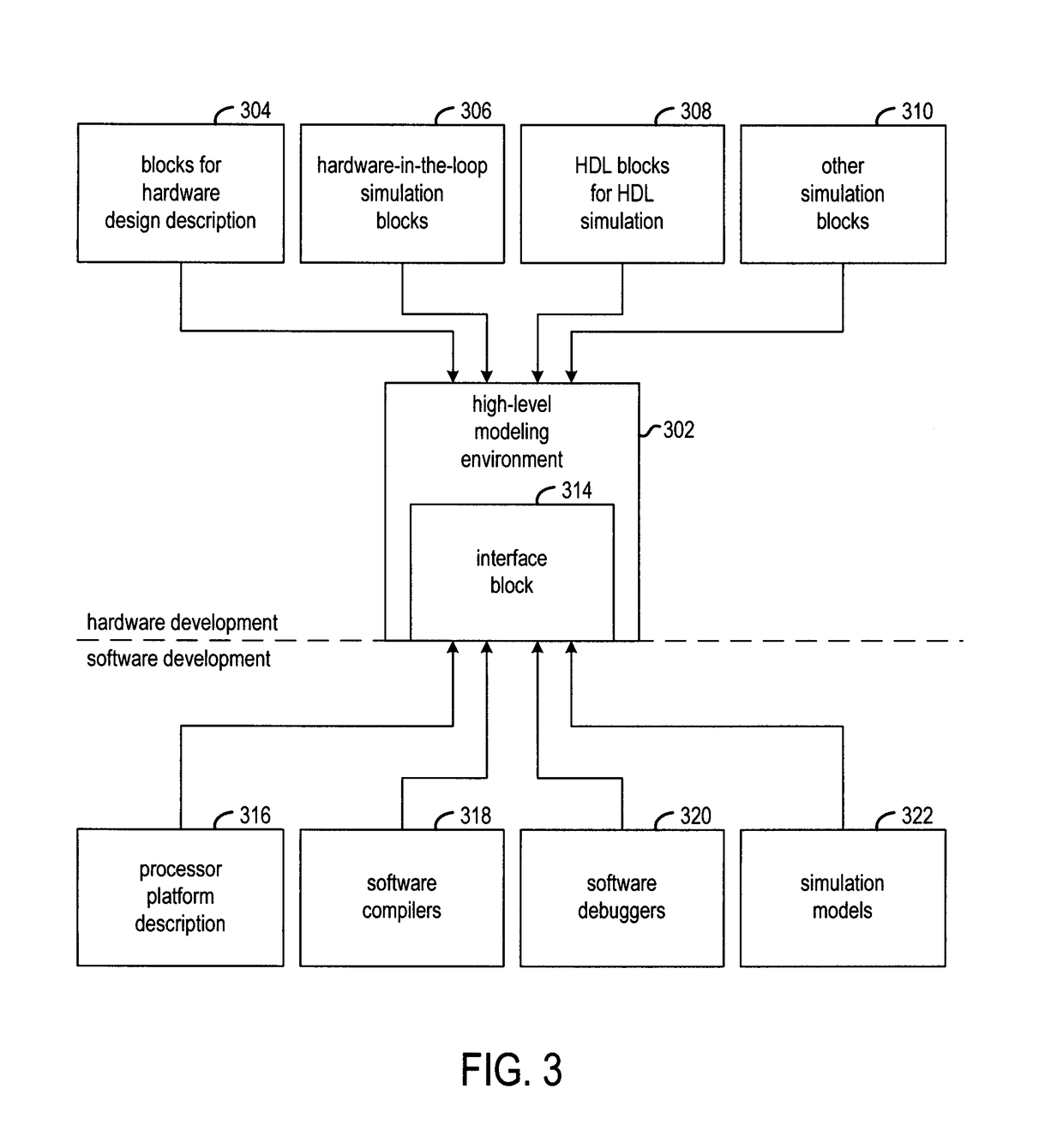
[0020]One embodiment of the invention is directed to an integrated design environment (IDE) that allows system-level application development of both custom hardware and software designs. Within the IDE, the end user can focus on specifying the high-level behavior of the target systems. In addition, the end user can simulate and debug the high-level description of the system.

[0021]Three co-simulation modes are supported for running various combinations of software simulations, hardware emulations, and / or a hardware-deployed implementation of a system. The modes include lock-step mode, asynchronous mode, and mixed mode. In lock-step mode, the hardware simulations and the software simulations are synchronized at each clock cycle. The lock-step co-simulation provides the user with cycle-accurate simulation information of the entire system. This is desired when the user is developing tightly coupled hardware and software components and the communication interfaces between them, and when ...


PUM


Abstract

Various approaches for co-simulating an electronic system design are described. In one approach, a hardware design function block in the design is instantiated, along with a specification of a software execution platform including external ports and software to execute on the platform. In response to a user instruction to import the software execution platform into the design, a software execution platform interface block is automatically instantiated. A first simulation model is generated from the hardware design function block and the software execution platform interface block and a second simulation model is generated from the software execution platform. The design is co-simulated using the first and second simulation models. Data is communicated between the first simulation model and the second simulation model via the interface block.

Description

FIELD OF THE INVENTION[0001]The present invention generally relates to tools for developing electronic system designs.BACKGROUND[0002]It is becoming common for electronic system designers to create designs including both field programmable gate arrays (FPGAs) and one or multiple general purpose or special purpose processors embedded in or attached to the FPGA devices. However, present tools provide little assistance in the overall design flow for both software and hardware components of the system.[0003]Various tools are used to create the hardware and software components of the system. For hardware parts of the system, high-level modeling system (HLMS) based design tools are becoming popular. These tools allow electronic designs to be described, assembled, and debugged at the high-level within a high-level modeling environment (e.g., MATLAB / Simulink and Ptolemy). As an important functionality, once the high-level modeling processing is completed, these HLMS based design tools can a...

Claims


Application Information

Patent Timeline
Patent Type & Authority Patents(United States)
IPC IPC(8): G06F17/50
CPCG06F17/5022G06F17/5027G06F2217/86G06F30/331G06F2117/08G06F30/33
Inventor OU, JINGZHAOMILNE, ROGER B.
Owner XILINX INC
Why Eureka
Try Eureka