High definition scintillation detector for medicine, homeland security and non-destructive evaluation

a scintillation detector and high-definition technology, applied in the field of x-ray imaging, can solve the problems of limiting the clinical utility of cardiac ct, unable to distinguish between vulnerable and stable plaques, and unable to perform non-invasive determination of coronary plaque composition, etc., to improve spatial resolution and dqe. , improve the spatial resolution of digital imaging

Inactive Publication Date: 2013-07-02
TRUSTEES OF BOSTON UNIV +1
View PDF13 Cites 14 Cited by
  • Summary
  • Abstract
  • Description
  • Claims
  • Application Information

AI Technical Summary

Benefits of technology

[0012]The present invention improves the spatial resolution of digital imaging to 1 micron or sub-micron level, while keeping the X-ray dose acceptable. It provides a new technology based on scintillation light confined to individual nano-fibers in a bundle that concomitantly improves the spatial resolution and DQE.
[0015]The X-ray imaging system using such an invention overcomes the deficiencies of the current systems as it improves light generation, and has higher light capture efficiency. It intrinsically rejects scatter, eliminates cross-talk between the guiding cores, and is self-collimating.

Problems solved by technology

Currently, the composition of a coronary plaque cannot be determined non-invasively and differentiation between vulnerable and stable plaque is not possible due to limited spatial resolution.
The presence of calcified coronary artery plaque is the most frequent reason for false positive evaluations, often leading to unnecessary additional testing hence limiting the clinical utility of cardiac CT.
It has been shown that dense calcium, due to the limited spatial resolution, creates a “spill-over” effect into adjacent, lower-intensity voxels.
The resulting “calcium blooming” obscures the coronary artery lumen and leads to an over-estimation of luminal stenosis.
In demanding applications such as space and aviation, non-destructive testing of engine parts and materials suffer from the same lack of higher spatial resolution and DQE.
As such “small animal imaging”, which currently means mice, is not of great use when imaging even smaller organisms such as fleas and fire-flies.

Method used


Image

  • High definition scintillation detector for medicine, homeland security and non-destructive evaluation
  • High definition scintillation detector for medicine, homeland security and non-destructive evaluation
  • High definition scintillation detector for medicine, homeland security and non-destructive evaluation

Examples


Embodiment Construction

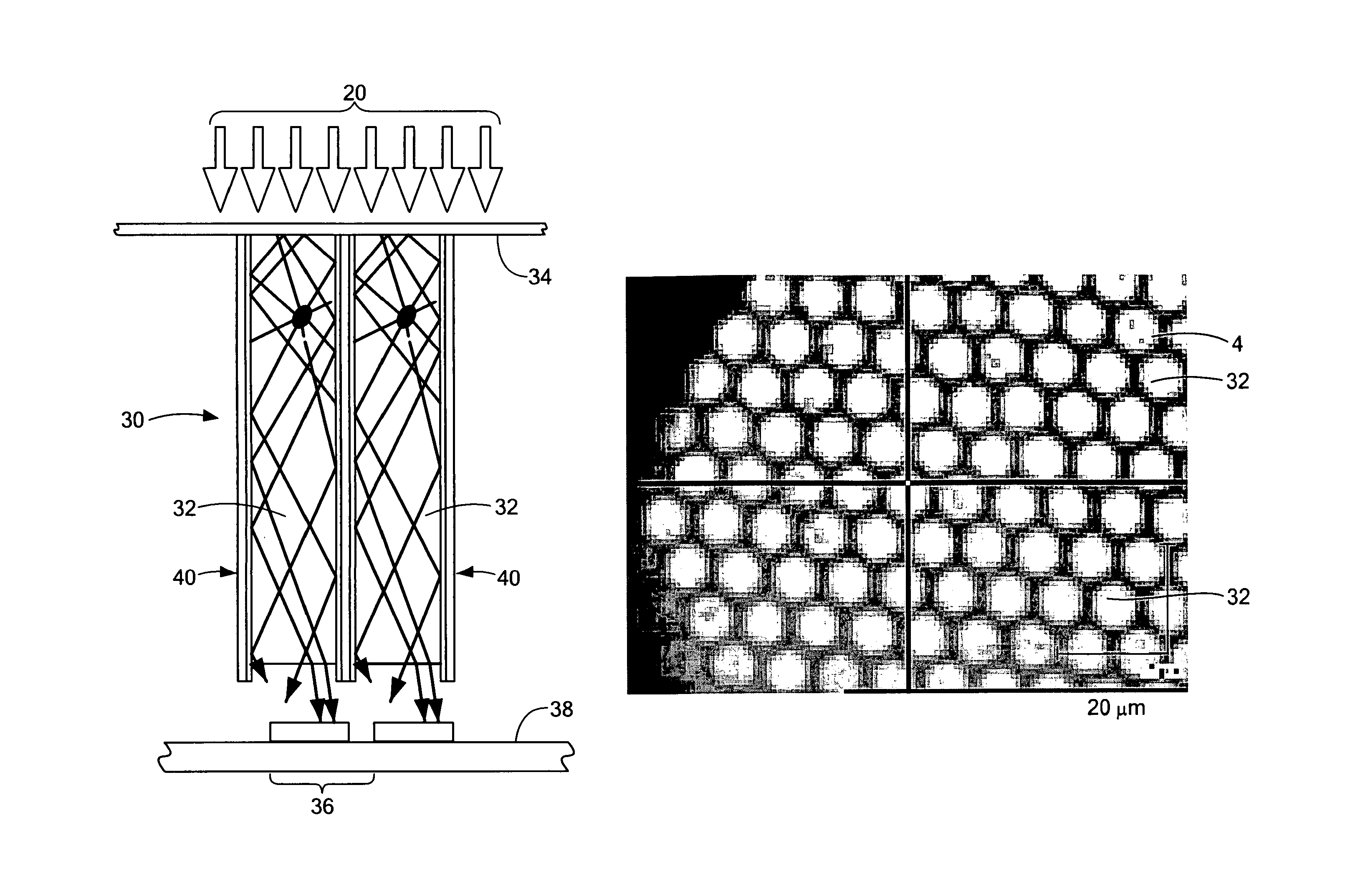
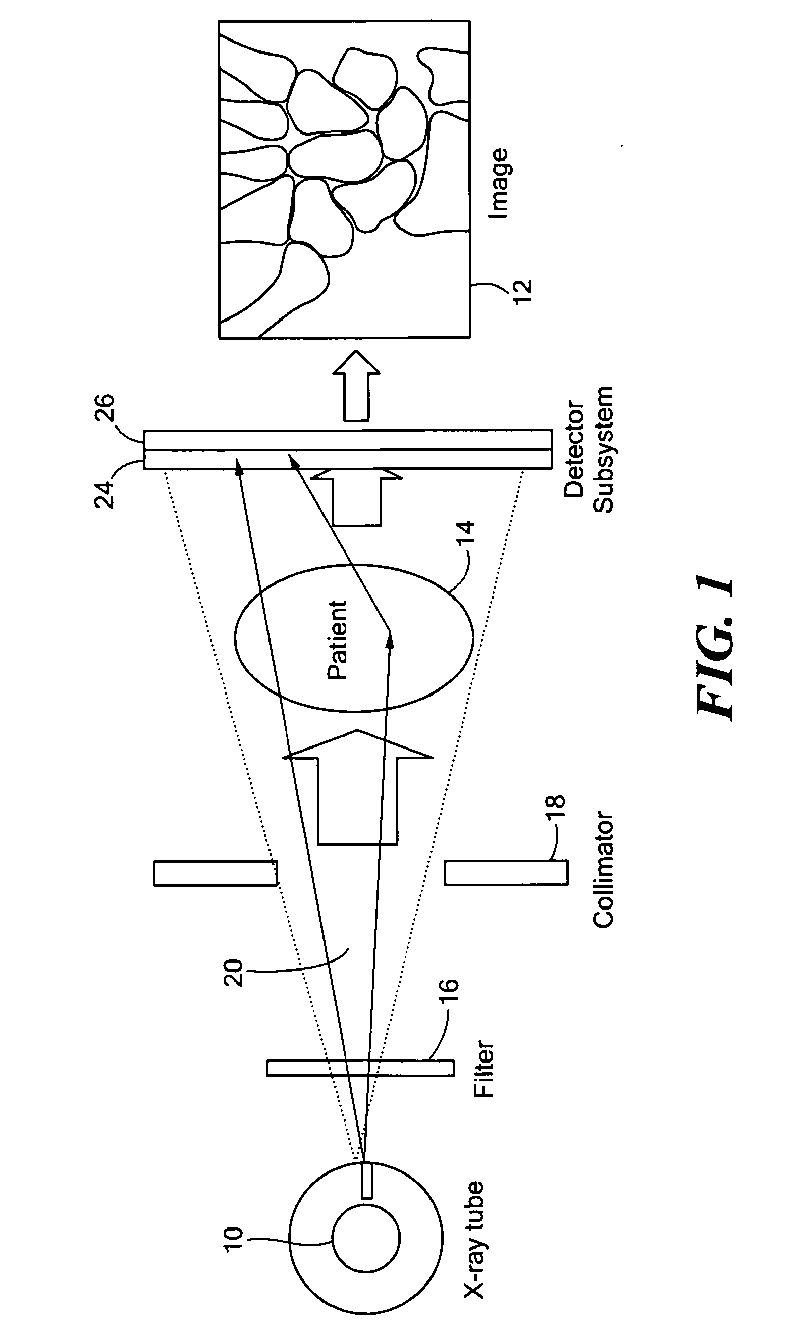
[0030]FIG. 1 shows the imaging chain of a typical imaging system from X-ray generation at source 10 to the final image produced by image processing electronics 12. The X-ray photons that are too low in energy to make it across a patient or other subject of study 14 are filtered out by a filter 16. The X-ray beam, after filtration, is collimated in a collimator 18 to limit the rays to passes through the patient or subject 14. The photon flux along the principle ray is attenuated in a density-dependent manner, thus imprinting the anatomical information in the subject 14 in the X-ray beam 20. A large fraction of the X-ray beam 20 traveling through the patent 14 is scattered and contributes significantly to X-ray dose and image noise.

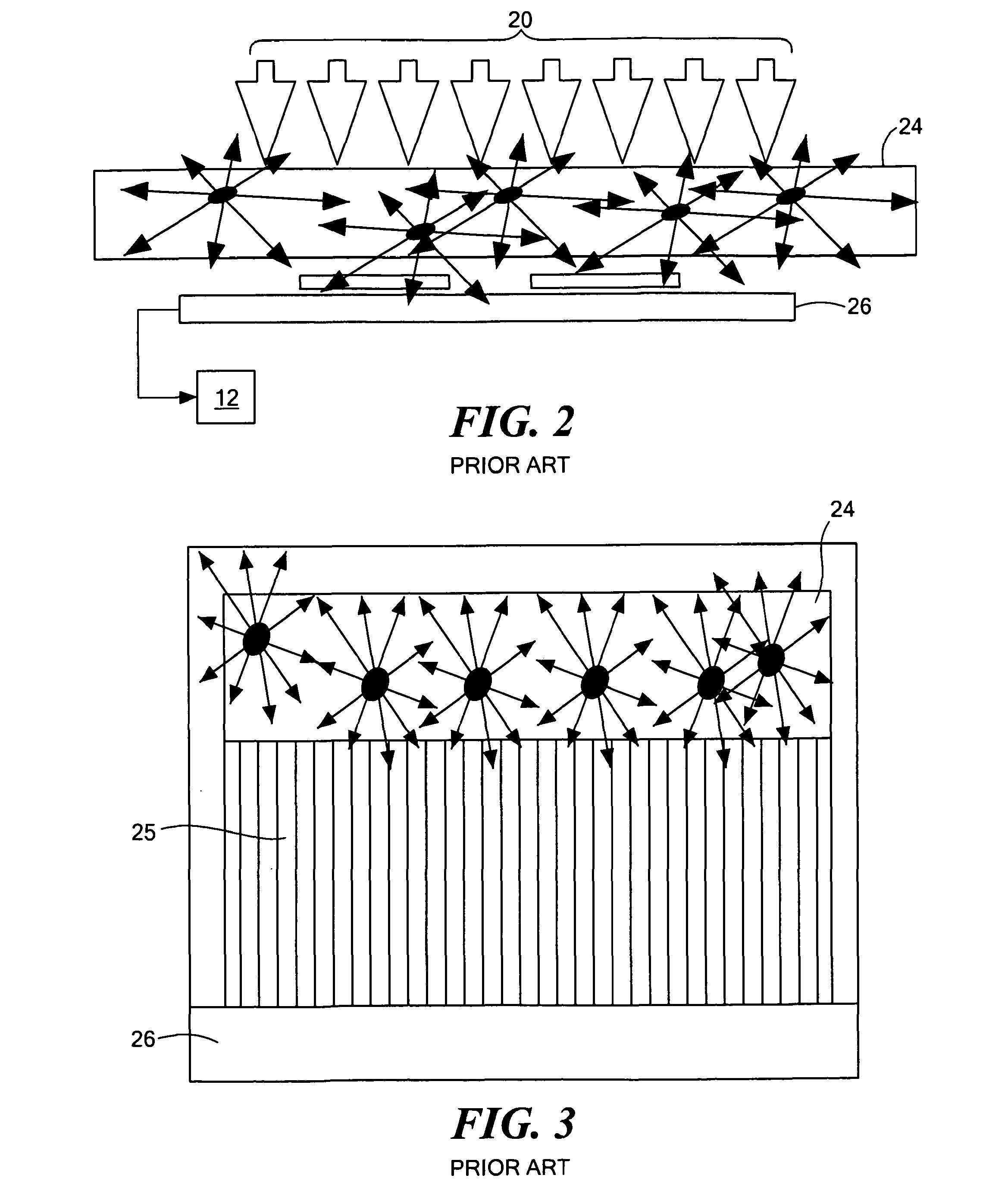
[0031]In the prior art, and as shown in FIG. 2, a digital detector subsystem 22 comprises a scintillation layer 24 typically grown on a semiconductor sensor layer 26 which converts X-ray energy directly into a digital image. A digital detector consists of a...


PUM


Abstract

A bundle of drawn fibers that have X-ray scintillating unagglommerated nanocrystallite particles in plastic or glass cores of down to 0.1 micron spacing and claddings of X-ray absorbing compounds in the cladding composition. Optional is a cover to the bundle that blocks light from leaving the bundle at the X-ray side while allowing X-rays to pass into the cores. To image the light exiting the fiber bundle at the sub-micron level, light expansion is preferable using either a lens system or a fiber bundle expander.

Description

CROSS REFERENCE TO RELATED APPLICATIONS[0001]This application claims priority to U.S. Provisional Application No. 60 / 904,973 filed Mar. 5, 2007.STATEMENT REGARDING FEDERALLY SPONSORED RESEARCH OR DEVELOPMENT[0002]This invention was made with Government Support under Contract No. FA9550-05-1-0107 awarded by Air Force Office of Scientific Research. The Government has certain rights in the invention.FIELD, BACKGROUND, AND MOTIVATION FOR THE INVENTION[0003]The present invention relates to X-ray imaging of very small formations within human as well as inanimate subjects and is aimed at improving the spatial resolution and the detective quantum efficiency (DQE) of X-ray detectors.[0004]Currently, the highest resolution of digital X-ray imaging systems is up to 25 microns. At this spatial resolution, many pathologies (e.g., micro calcifications in breast cancer) are too small to be visualized at an early stage. In mammography, the resolution of present digital machines is of the order of 5...

Claims


Application Information

Patent Timeline
Patent Type & Authority Patents(United States)
IPC IPC(8): G01T1/203H05G1/64
CPCG01T1/16G01T1/201
Inventor MORSE, THEODORE F.GUPTA, RAJIVROBERTS, CARSON B.CHIVAS, ROBERT D.
Owner TRUSTEES OF BOSTON UNIV
Why Eureka
Try Eureka