Measuring probes for measuring and taking samples with a metal melt

a technology of measuring probes and metal melts, which is applied in the direction of fluid pressure measurement, manufacturing converters, instruments, etc., can solve the problems of not always easy sampling types, and achieve the effect of simplifying the removal of the sample from the measuring probe and improving the sample quality

Active Publication Date: 2013-07-09
HERAEUS ELECTRO NITE INT NV
View PDF34 Cites 10 Cited by
  • Summary
  • Abstract
  • Description
  • Claims
  • Application Information

AI Technical Summary

Benefits of technology

[0010]Accordingly, the invention is based on the object of improving the existing measuring probes and samplers and facilitating largely gas-free sampling, i.e. to improve the sample quality. Preferably, the removal of the sample from the measuring probe should be simplified as well.
[0011]The object is achieved according to one embodiment of the invention in a measuring probe for measuring and taking samples in a metal melt, the probe having a measuring head arranged on a lance, wherein the measuring head carries at least a temperature sensor and a sampling chamber, wherein the sampling chamber is surrounded, at least partially, by the measuring head and includes an intake duct that extends through the measuring head and is preferably made of a quartz glass tube. In this embodiment the probe will allow for excellent, gas bubble-free samples if the ratio of the length L of a section of the quartz glass tube, which extends in the measuring head, and the square of a minimum diameter D of the quartz glass tube at least at one site in the inner section is L / D2<0.6 mm−1.
[0012]This ratio is preferably <0.45 mm−1, and particularly preferably is <0.3 mm−1. At low over-heating of the metal melt, a low ratio has proven to be advantageous, for example a ratio of L / D2<0.6 mm−1 at an over-heating of >100° C. and a ratio of L / D2<0.3 mm−1 at an over-heating of <80° C.

Problems solved by technology

This type of taking a sample is not always easy, in particular during the blowing process in the converter, since the theoretical density of the steel melt varies strongly, on the one hand, due to the oxygen blowing process from above and, on the other hand, due to inert gas being blown in through the converter floor.

Method used


Image

  • Measuring probes for measuring and taking samples with a metal melt
  • Measuring probes for measuring and taking samples with a metal melt
  • Measuring probes for measuring and taking samples with a metal melt

Examples


Embodiment Construction

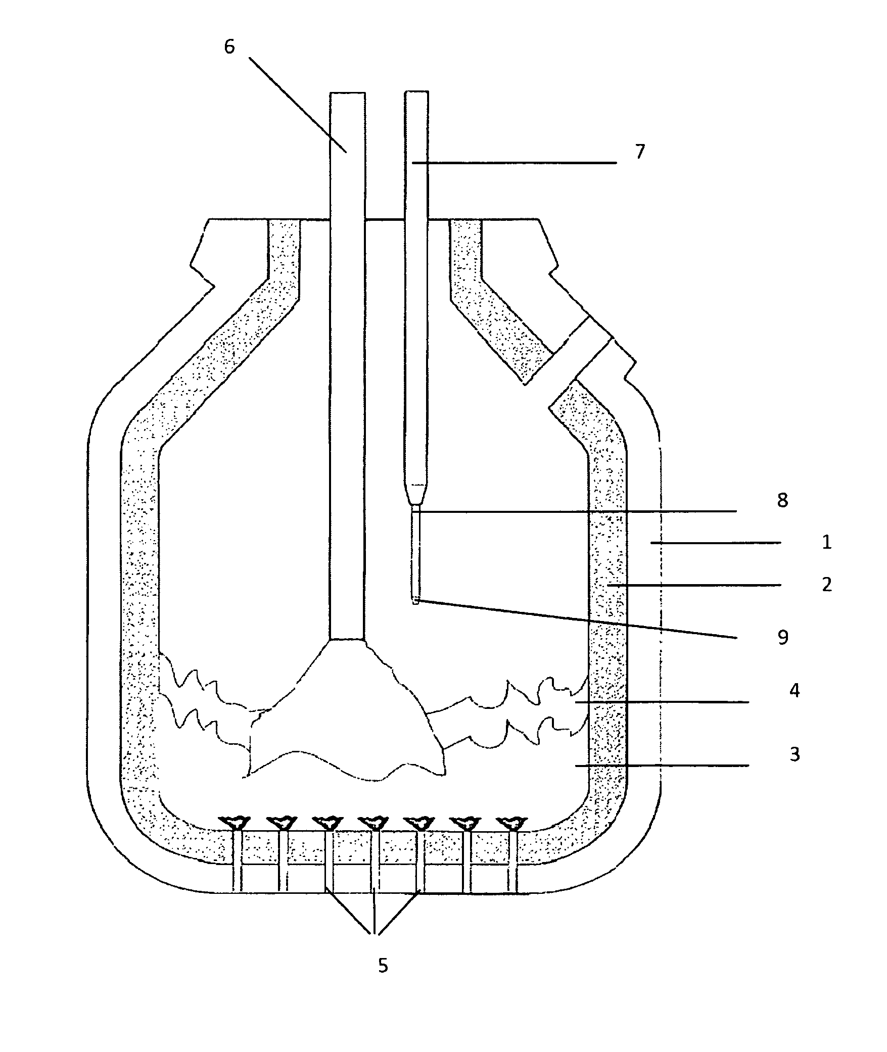
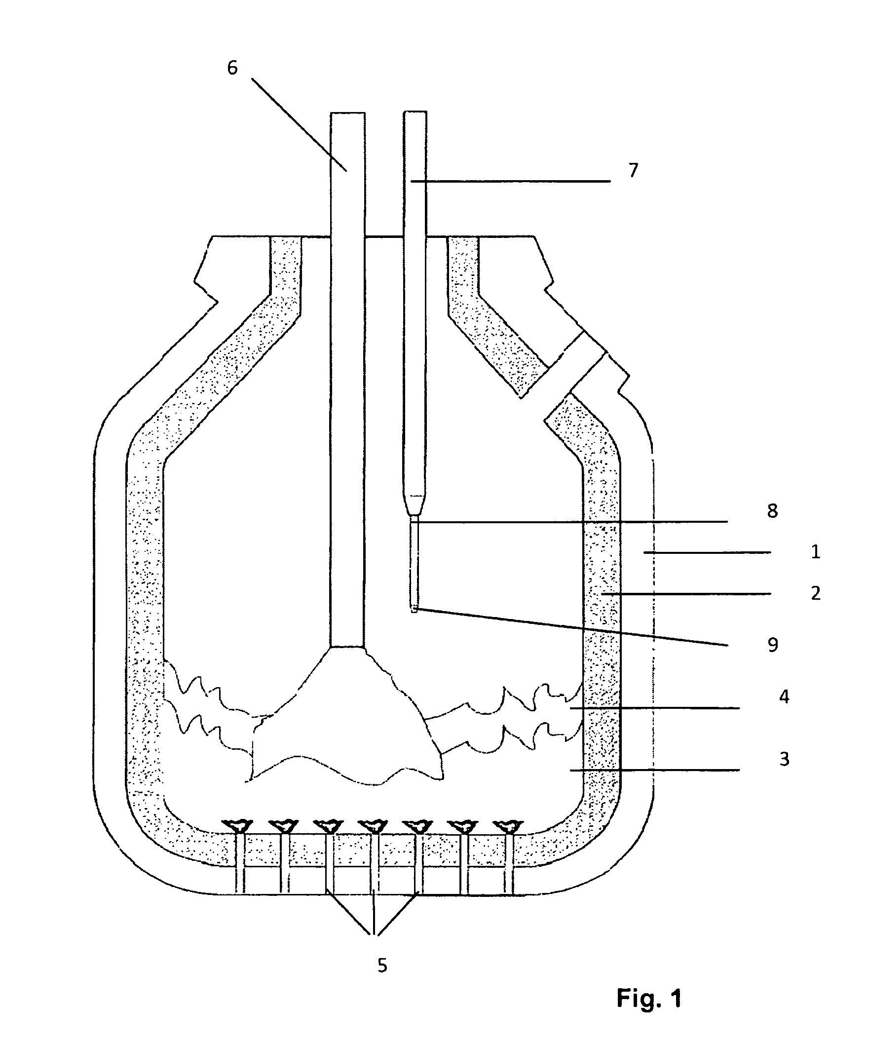
[0027]FIG. 1 shows a converter 1 having a lining 2. The converter 1 contains a steel melt 3 on which a slag layer 4 is situated. For steel-making, argon is blown through the floor of the converter 1 through floor nozzles 5 into the metal melt. Oxygen is blown in from above by a blowing lance 6. Aside from the blowing lance 6, a so-called immersion lance 7, which has a measuring probe 8 having a measuring head 9 arranged on its immersion end, is introduced into the converter 1. The measuring process proceeds while oxygen is being blown in, usually approximately 2 minutes before the end of the oxygen blowing process. This involves measuring the temperature and taking a sample for determination of the carbon content. The results of the measurements allow the blowing model to be corrected in order to be able to alter the quality of the steel melt.

[0028]A second measurement may be performed after completion of the oxygen blowing process. This usually involves measuring the temperature an...


PUM

PropertyMeasurementUnit
pressureaaaaaaaaaa
counter-pressureaaaaaaaaaa

Abstract

A measuring probe is provided for measuring and taking samples in a metal melt. The probe has a measuring head arranged on a lance, wherein the measuring head carries at least a temperature sensor and a sampling chamber, and wherein the sampling chamber is surrounded, at least partially, by the measuring head and includes an intake duct that extends through the measuring head. The intake duct includes an inner section, which extends in the measuring head and has a length L and a minimum diameter D at least at one site in the inner section. The ratio L / D2 is less than 0.6 mm−1.

Description

BACKGROUND OF THE INVENTION[0001]The invention relates to measuring probes for measuring and taking samples with a metal melt, the probe having a measuring head arranged on a lance, wherein the measuring head carries at least a temperature sensor and a sampling chamber, and wherein the sampling chamber is surrounded by the measuring head and includes an intake duct made of a quartz glass tube that extends through the measuring head.[0002]Measuring probes of this type are known in principle and are used, among other uses, in steel-making in so-called converters or in electric arc furnaces.[0003]In a converter (so-called BOF converter—technical term for basic oxygen furnace), a lance is used to blow oxygen into the metal melt. The converter is lined with refractory material, which withstands the erosion due to slag and heat during the oxygen blowing process in an optimal manner. Scrap metal and limestone (calcium oxide) are added into the converter in order to cool the melt and remove...

Claims


Application Information

Patent Timeline
Patent Type & Authority Patents(United States)
IPC IPC(8): G01L7/00G01D21/00
CPCG01N33/206G01N1/125G01N33/205Y02P10/20C21C5/4606C21C5/462C21C5/4673
Inventor NEYENS, GUIDO JACOBUSBEYENS, DRIES
Owner HERAEUS ELECTRO NITE INT NV
Why Eureka
Try Eureka