Method for cooling a four stroke marine engine with multiple path coolant flow through its cylinder head

a technology of cylinder head and cooling cylinder, which is applied in the direction of marine propulsion, motor-driven power plants, vessel construction, etc., can solve the problem of overcooling of certain parts of the engin

Active Publication Date: 2013-07-09
BRUNSWICK CORPORATION
View PDF31 Cites 27 Cited by
  • Summary
  • Abstract
  • Description
  • Claims
  • Application Information

AI Technical Summary

Problems solved by technology

The use of cold water can often result in the overcooling of certain portions of the engine and, as a result, the condensing of fuel vapor which can dilute the oil supply of the engine with liquid fuel.
The disadvantages of oil dilution are well known to those skilled in the art of marine engines as are the various types of damage that can result from it.
Other problems associated with cooling marine engines relate to the direction of cooling water as it flows through engine components.

Method used


Image

  • Method for cooling a four stroke marine engine with multiple path coolant flow through its cylinder head
  • Method for cooling a four stroke marine engine with multiple path coolant flow through its cylinder head
  • Method for cooling a four stroke marine engine with multiple path coolant flow through its cylinder head

Examples


Embodiment Construction

[0028]Throughout the description of the preferred embodiment of the present invention, like components will be identified by like reference numerals.

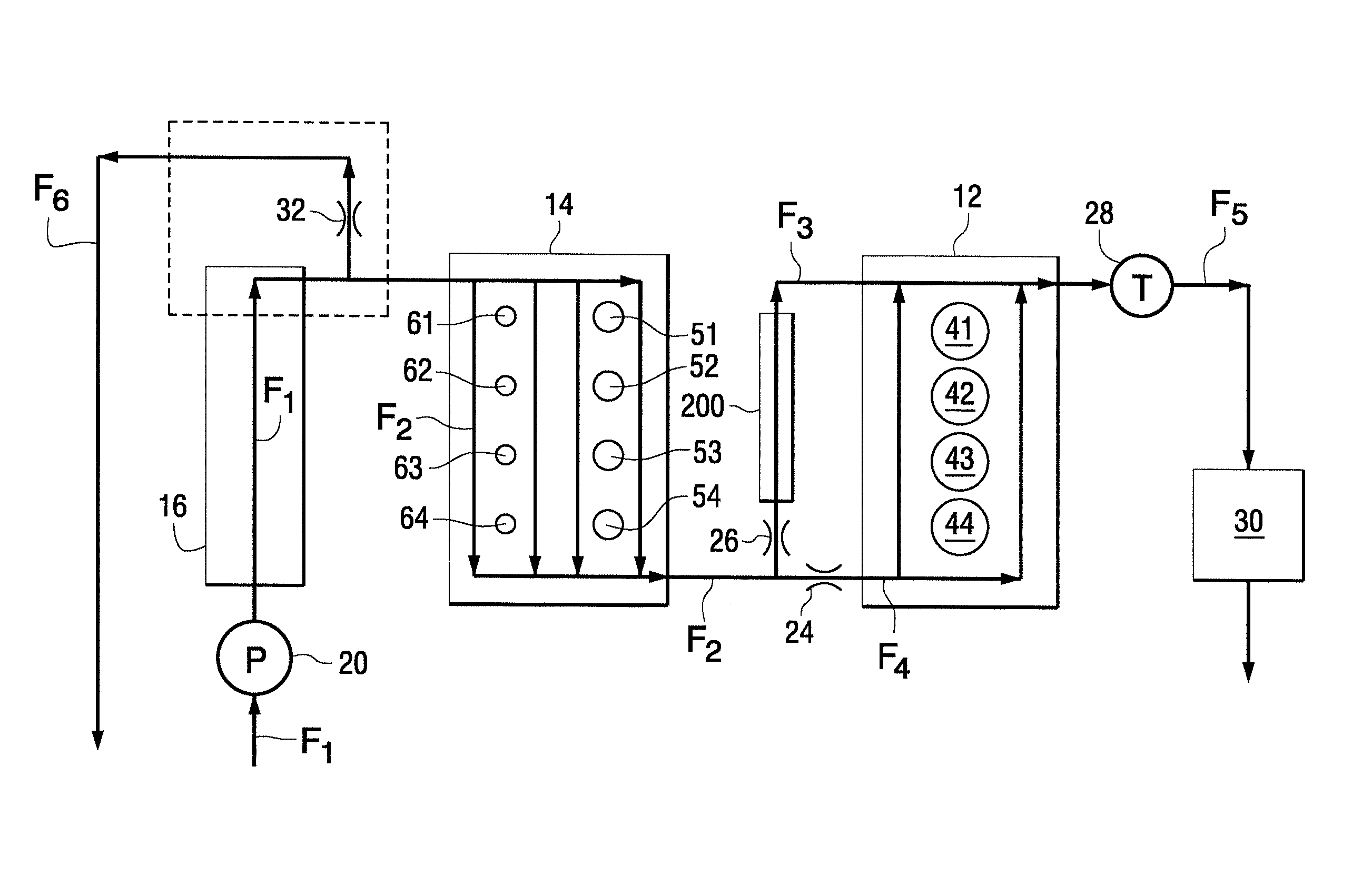
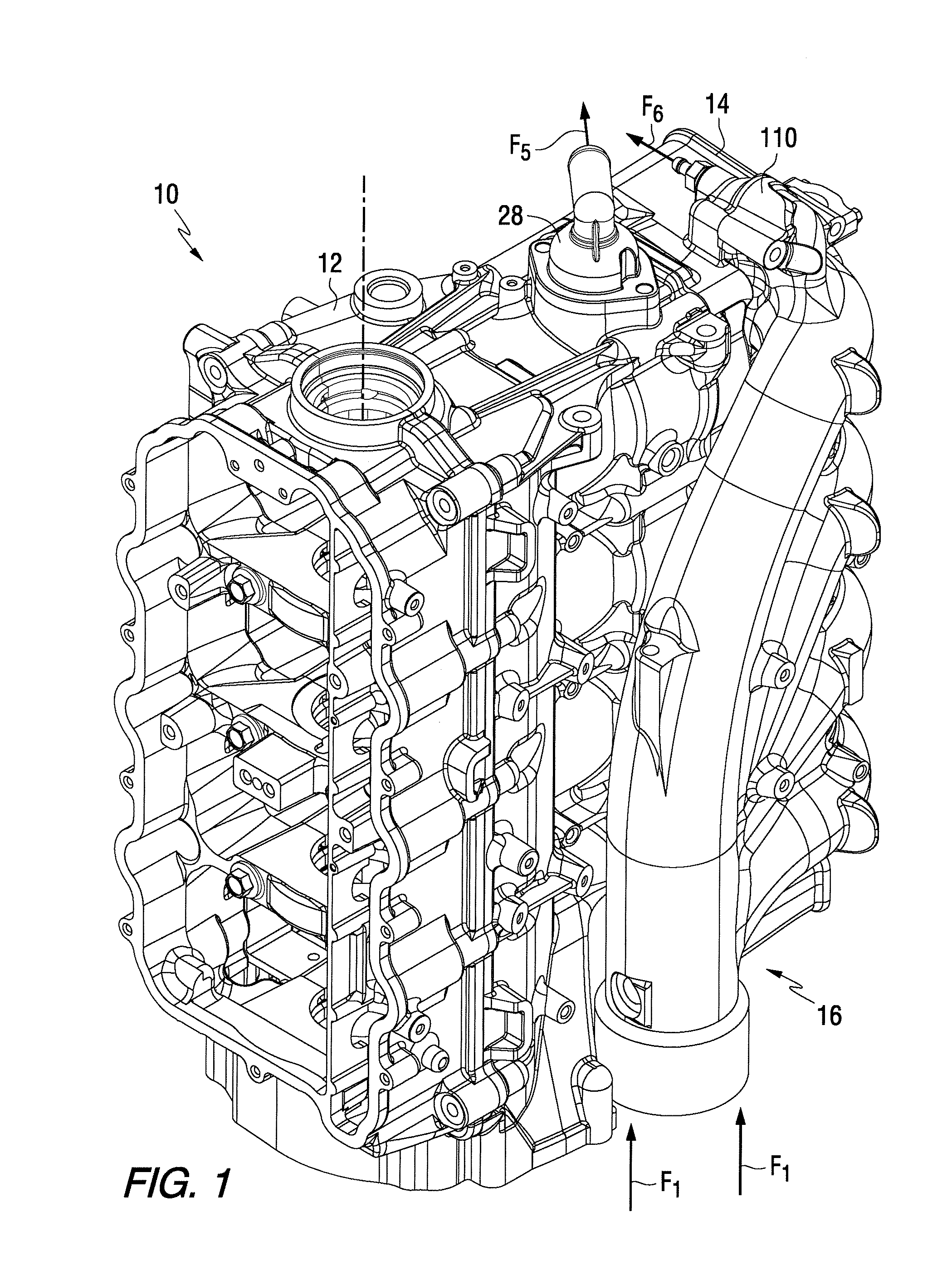
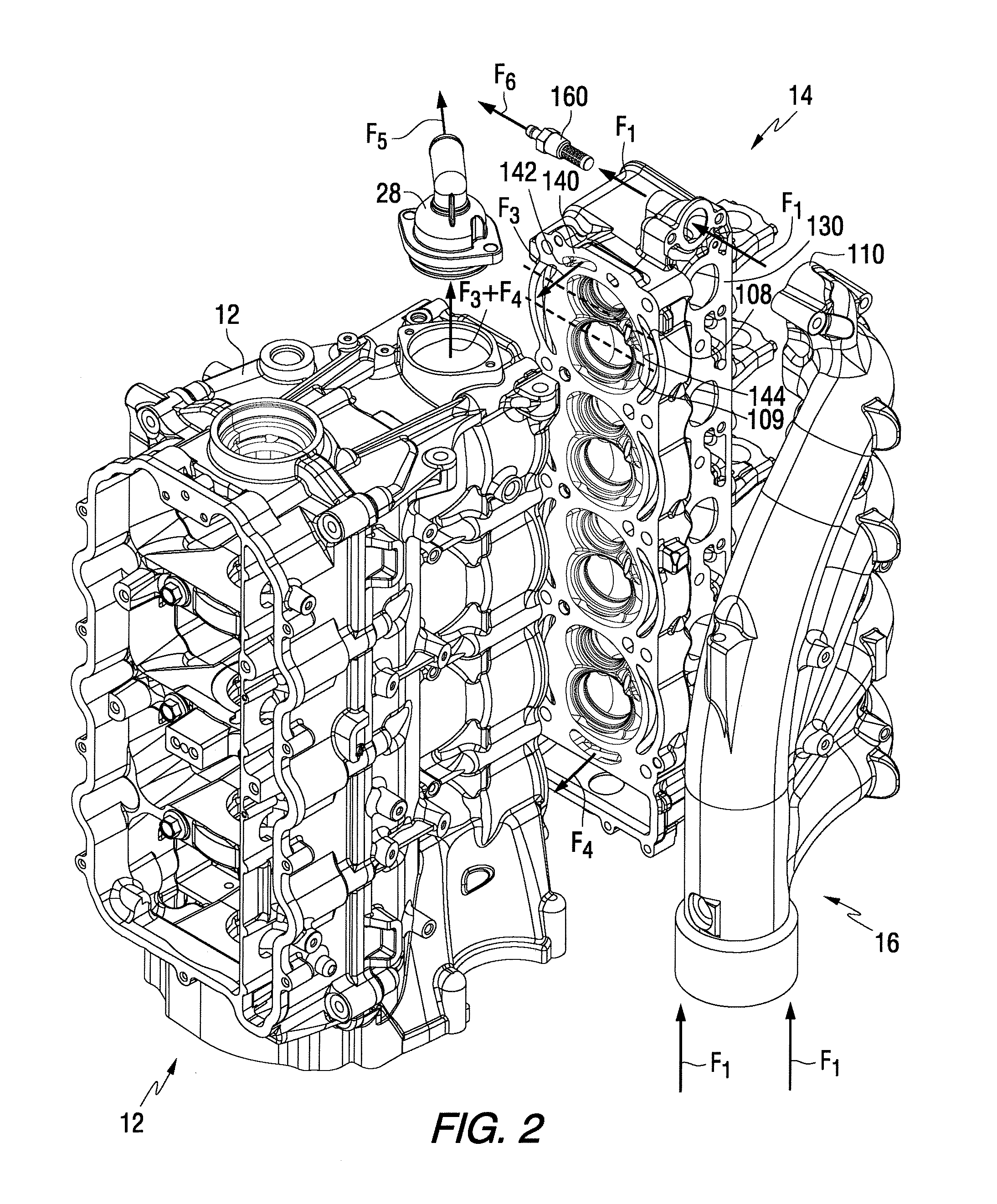
[0029]In conjunction with the following description of the various embodiments of the present invention, FIG. 1 is an isometric view of a marine engine. FIG. 2 is an exploded isometric view of the marine engine shown in FIG. 1 and shows the block 12 of the engine separated from the cylinder head 14 and exhaust manifold 16 of the engine. FIG. 3 is a highly simplified schematic representation of a marine engine system which is generally similar to the engine illustrated in FIGS. 1 and 2 and configured to comprise various preferred embodiments of the present invention. FIGS. 4-6 illustrate various marine engine configurations that are known to those skilled in the art. These known engine configurations will be described below in order to more clearly illustrate certain characteristics and features of the preferred embodiments of the presen...


PUM


Abstract

A cooling system for a marine engine is provided with various cooling channels which allow the advantageous removal of heat at different rates from different portions of the engine. A split flow of water is conducted through the cylinder head, in opposite directions, to individually cool the exhaust port and intake ports at different rates. This increases the velocity of coolant flow in the downward direction through the cylinder head to avoid the accumulation of air bubbles and the formation of air pockets that could otherwise cause hot spots within the cylinder head. A parallel coolant path is provided so that a certain quantity of water can bypass the engine block and avoid overcooling the cylinder walls.

Description

CROSS REFERENCE TO RELATED APPLICATIONS[0001]The present application is related to patent application Ser. No. 12 / 468,412 which was filed on the same date as the present application.BACKGROUND OF THE INVENTION[0002]1. Field of the Invention[0003]The present invention is generally related to a method for cooling a marine engine and, more particularly, to a method for directing coolant through a multiple pass path through its cylinder head.[0004]2. Description of the Related Art[0005]Those skilled in the art of marine engines are familiar with many different types of cooling systems and many different techniques for removing heat from various heat emitting components of marine propulsion systems. Those skilled artisans are also familiar with many important issues associated with the removal of heat from marine engines. Not only is it important to avoid the overheating of various components and devices of a marine propulsion system, but it is also very important to avoid the removal of...

Claims


Application Information

Patent Timeline
Patent Type & Authority Patents(United States)
IPC IPC(8): F01P3/20
CPCF01P3/202
Inventor TAYLOR, CHRISTOPHER J.REID, TIMOTHY S.TOWNE, WILLIAM J.BELTER, DAVID J.LANGENFELD, GREGG D.
Owner BRUNSWICK CORPORATION
Why Eureka
Try Eureka