Electrostatic motor including an actuator

a technology of electrostatic actuator and actuator, which is applied in the direction of generating/distributing signals, instruments, horology, etc., can solve the problems of not being able to vary the output voltage independently of the duration of output pulses, and not being optimal in terms of energy saving, so as to reduce power consumption

Active Publication Date: 2013-07-09
ETA SA MFG HORLOGERE SUISSE
View PDF9 Cites 5 Cited by
  • Summary
  • Abstract
  • Description
  • Claims
  • Application Information

AI Technical Summary

Benefits of technology

[0009]It is an object of the present invention to answer the aforementioned drawbacks by providing an electrostatic motor that includes an electrostatic actuator and in which the motor is driven with reduced power consumption.
[0014]This solution has the great advantage of being a compromise between a very short pulse duration with a high voltage, and a very long pulse duration with a low voltage. Indeed, on the one hand, as the parasitic capacitances are charged with the energy supplied by the voltage generator, the lower the voltage, the less energy is lost. On the other hand, the longer the pulse duration, the greater the charge of the actuator's electrode structures. It is thus also important to maintain as short a pulse duration as possible to reduce electrostatic losses to a minimum in the actuator's electrodes. The solution thereof lies in a compromise consisting in having the lowest possible voltage for an optimised pulse duration, applied for a given ratio between the parasitic capacitance and the active capacitance.
[0015]According to an advantageous embodiment, the actuator electrode structures are charged by a charge pump connected to supply terminals of the actuator, the charge pump being disconnected when the optimum instantaneous capacitance is reached. This solution ensures that the energy lost outside the motor actuation phases is minimal.

Problems solved by technology

This is far from being optimal in terms of energy saving.
In particular, it is not possible to vary the output voltage independently of the duration of the output pulses.

Method used


Image

  • Electrostatic motor including an actuator
  • Electrostatic motor including an actuator
  • Electrostatic motor including an actuator

Examples


Embodiment Construction

[0022]The invention will be described below solely by way of non-limiting example with reference to FIGS. 1 to 4.

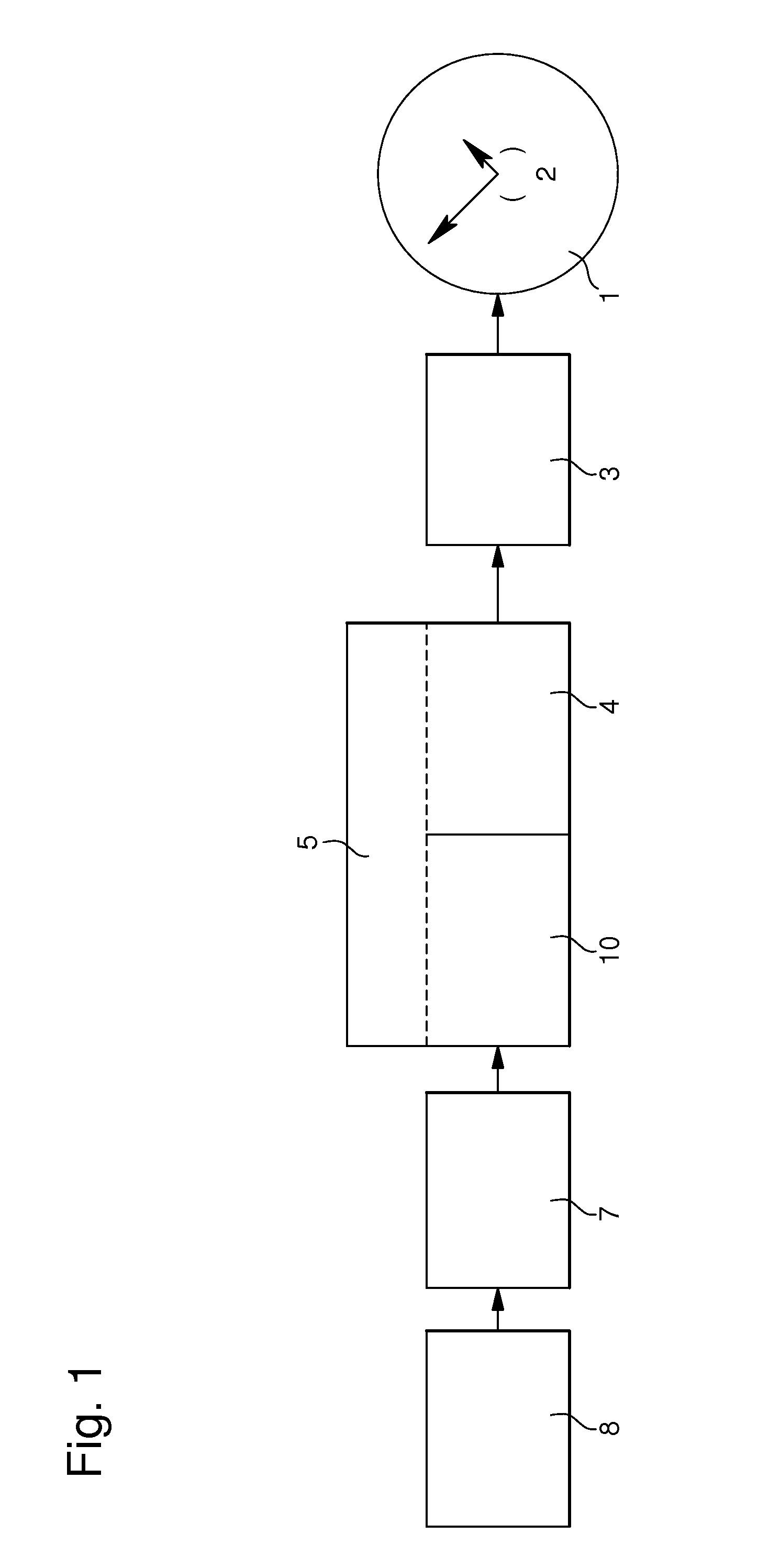
[0023]In FIG. 1, a timepiece is shown in the form of a block diagram, showing in particular the elements related to the present invention. This timepiece includes a dial 1 fitted with hands 2 indicating time information. The hands are driven by a set of gears 3 meshing with a mechanical interface 4 of an electrostatic motor 5. The motor is actuated via an electrostatic actuator 10. The actuator is powered by electric pulses which, in this example, are obtained by means of a charge pump 8 controlled by electronic means 7. Advantageously, elements 4, 5, 7, 8 and 10 shown in FIG. 1 are integrated.

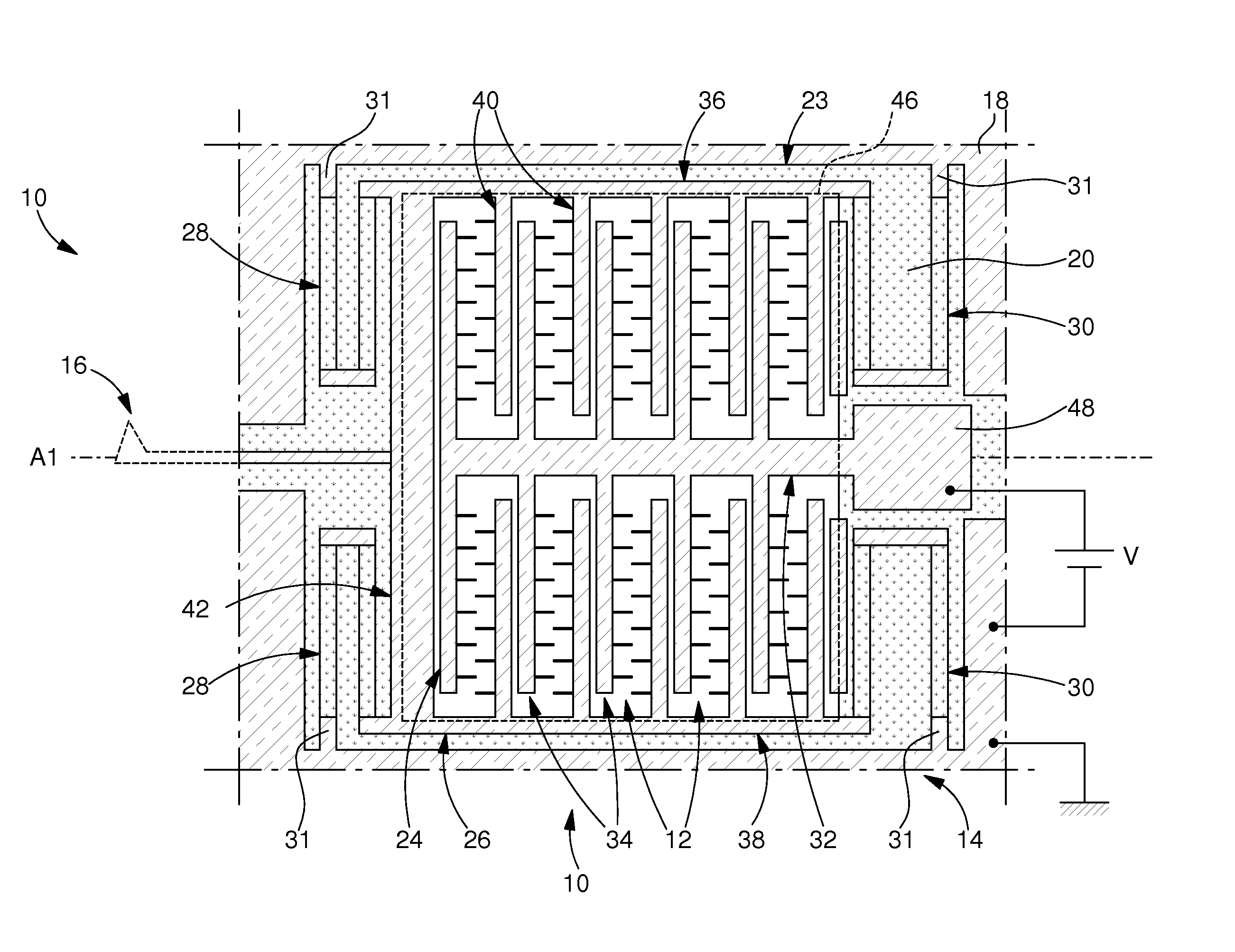
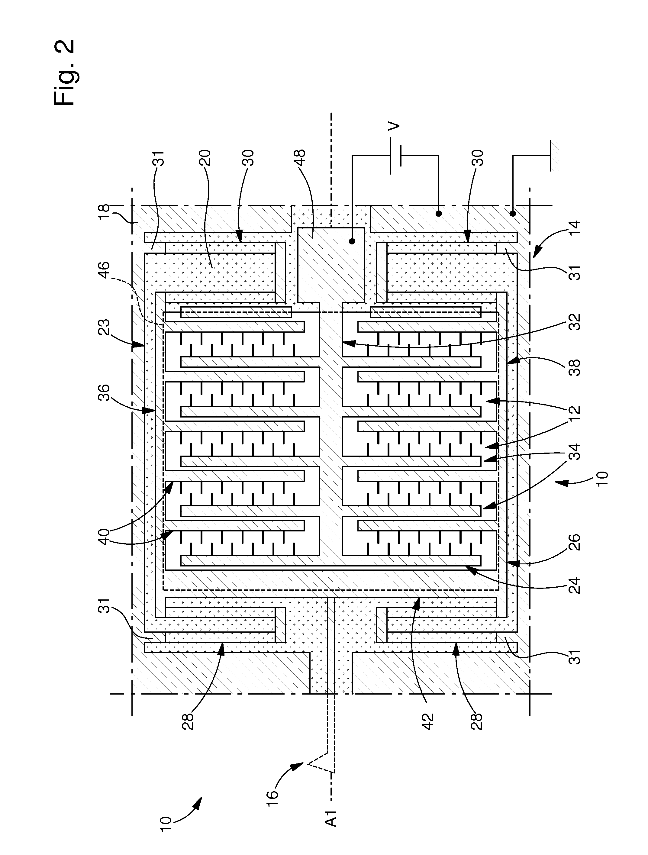
[0024]FIGS. 2 and 3 show, by way of example, a particular embodiment of an electrostatic actuator 10 with interdigited combs 12 capable of driving electrostatic motor 5 of FIG. 1. Actuator 10 is etched in a plate of crystalline or amorphous material, such as a silicon wafer. This ac...


PUM


Abstract

The electrostatic motor includes an electrostatic actuator (10) and a pulse generator (7, 8) for actuating said actuator with sufficient energy to drive the motor, the pulse generator is adapted to determine a pulse voltage level (UD) and a shortened pulse duration that is a function of the determined voltage level (UD) and the electric energy necessary for driving the motor and a function of parasitic capacitances (CP) and the maximum capacitance (Cact<sub2>—< / sub2>m) of the actuator in order to reduce electrostatic losses in the actuator.

Description

[0001]This application claims priority from European Patent Application No. 08164414.8, filed Sep. 16, 2008, the entire disclosure of which is incorporated herein by reference.FIELD OF THE INVENTION[0002]The present invention generally concerns an electrostatic motor for incorporation, in particular, in a timepiece to drive the movement thereof. The invention concerns, more specifically, an electrostatic motor including an electrostatic actuator, for example of the type with interdigited combs.BACKGROUND OF THE INVENTION[0003]There is known in the prior art, in particular from WO Patent No. 2004 / 081695, and corresponding U.S. equivalent publication U.S. Patent Application Publication No. US 2007 / 0069604 A1, both of which are incorporated herein by reference, a micro-motor made in a silicon wafer. In that document, the motor is made by etching a silicon layer. It includes a toothed drive wheel and actuating fingers, which cooperate with the teeth of the wheel to cause it to rotate. E...

Claims


Application Information

Patent Timeline
Patent Type & Authority Patents(United States)
IPC IPC(8): G04F5/00
CPCG04C3/08H02N1/008H02N1/00
Inventor BISIG, MARTIN
Owner ETA SA MFG HORLOGERE SUISSE
Why Eureka
Try Eureka