Agitation apparatus and agitation method

a technology of agitation apparatus and agitation method, which is applied in the direction of rotary stirring mixers, manufacturing tools, transportation and packaging, etc., can solve the problems of insufficient mixing, insufficient mixing, and generation of hammers, so as to reduce the adhesion of a substance, and reduce the risk of insufficient mixing

Active Publication Date: 2013-07-16
DAINIPPON INK & CHEM INC
View PDF38 Cites 12 Cited by
  • Summary
  • Abstract
  • Description
  • Claims
  • Application Information

AI Technical Summary

Benefits of technology

[0027]An agitation apparatus 1 according to the present invention generates a vortex flow through rotation of an agitation blade and produces a plurality of small vortex flows rotating (spinning) in the opposite direction to the rotating direction of the vortex flow. The agitation apparatus 1 also forms a vertically circulating flow having a curved section above a lower blade, which is a flow of a particular shape that cannot be observed in a conventional agitation apparatus, throughout an agitation vessel. Synergetic effects of these flows ensure rapid, efficient (low-power consuming), and homogeneous mixing of fluids with a wide spectrum of viscosities from low to high levels and fluids with a great difference in viscosity. Further, by avoiding the risk of insufficient mixing caused by adhesion of powder and decreasing adhesion of a substance to be agitated to a blade, yield is increased and cleansing and maintenance work are facilitated.
[0028]The agitation apparatus 11 according to the present invention generates a vortex flow through rotation of an agitation blade and produces a plurality of small vortex flows rotating (spinning) in the opposite direction to the rotating direction of the vortex flow. The agitation apparatus 11 also forms a vertically circulating flow having a curved section above a lower blade throughout an agitation vessel. An outer blade portion of an upper agitation blade brings about effects of scraping off and raising the fluid in the vicinity of an inner wall surface of the agitation vessel. An inner blade portion of the upper agitation blade exerts an effect of depressing the fluid in the vicinity of a central portion of the agitation vessel. The proximity of the joint portion between the inner blade portion and the outer blade portion causes effects of dividing, reversing, and merging outward flows. These effects and synergetic effects of the effects ensure rapid, efficient, and homogeneous mixing of fluids with a wide spectrum of viscosities from low to high levels, fluids with high thixotropy, fluids with high viscosity and high thixotropy, and fluids with a great difference in viscosity.

Problems solved by technology

However, it has been known that small-sized blades easily produce a flow boundary in an agitation vessel, which not only hampers generation of a vertically circulating flow throughout the vessel but also causes insufficient mixing when fluid with high viscosity is processed.
Contrastingly, as has been known, the anchor blades or the ribbon blades cause insufficient mixing due to simultaneous revolution when fluid with low viscosity is processed.
Particularly, when the small-sized blades are employed to agitate a highly thixotropic fluid, the fluid is flowable only in the proximities of the blades but not in ranges spaced from the blades, which are the vicinities of the inner wall and the bottom portion of the agitation vessel, thus causing insufficient mixing.
Also in this case, mixing becomes insufficient.
Accordingly, the aforementioned agitation blades all increase risks of insufficient mixing and incomplete reaction when such a chemical reaction that the viscosity of a substance to be processed greatly changes is brought about in the agitation vessel or a highly thixotropic substance to be processed is mixed and caused to react in the agitation vessel.

Method used


Image

  • Agitation apparatus and agitation method
  • Agitation apparatus and agitation method
  • Agitation apparatus and agitation method

Examples


example 1

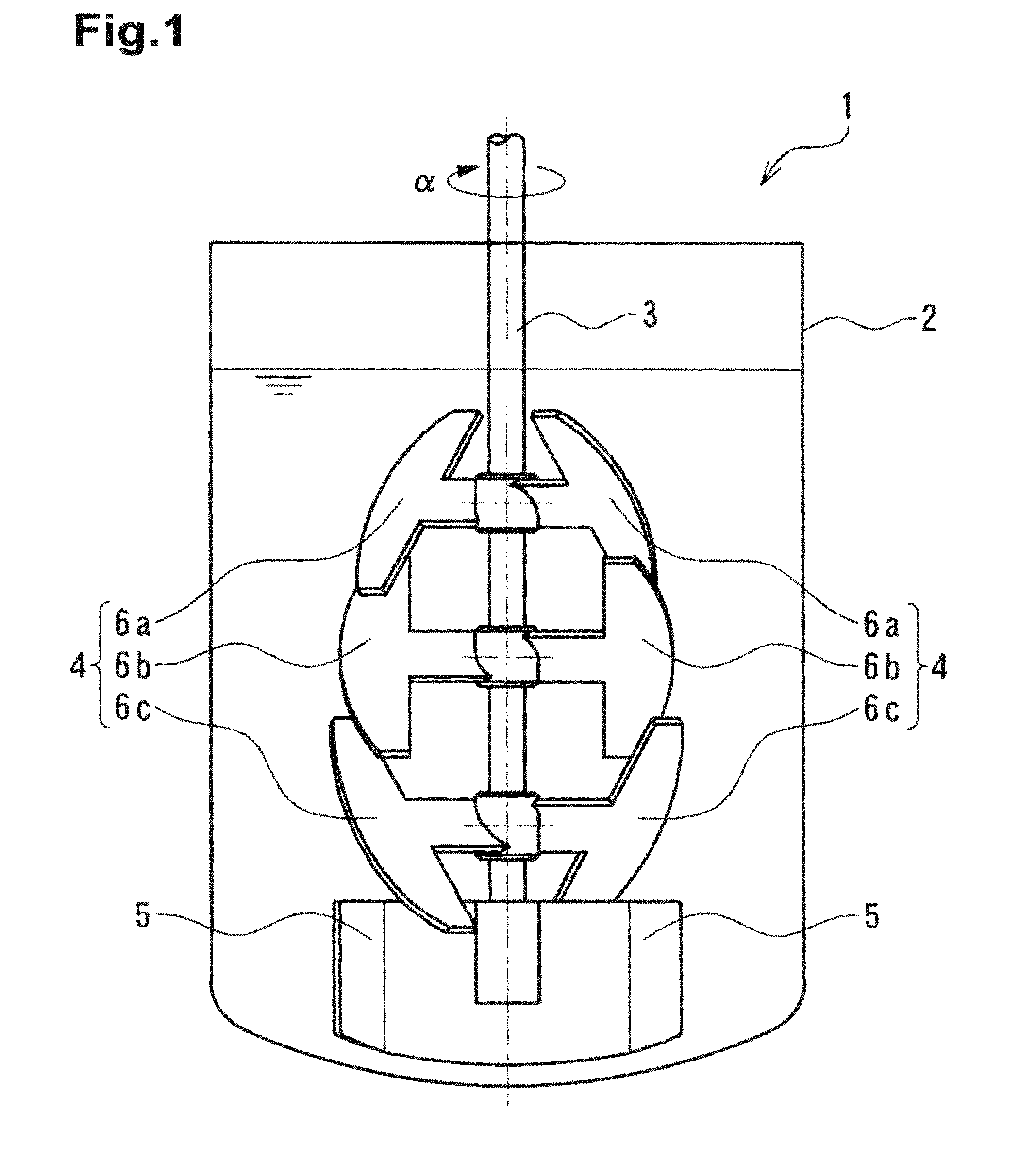
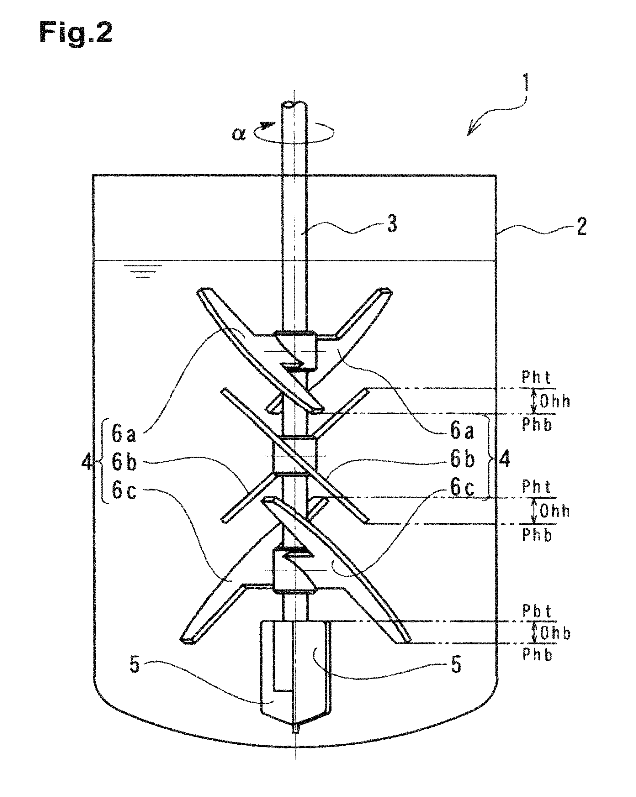
[0198]A solution of starch syrup at 5 Pa·s colored with iodine was decolorized with a solution of sodium thiosulfate prepared with the viscosity equal to that of the starch syrup solution and using starch syrup. The time (a mixing completion time) until the color of the iodine completely disappeared was measured. Specifically, 2 L of the aforementioned colored starch syrup solution was poured into a flask with the inner diameter φ130 mm. The agitation apparatus 1 of the present embodiment, as illustrated in FIGS. 1 to 3, was set and the number of rotation was adjusted so that the agitation power was 1.5 kW / m3. Specifically, the number of rotation was 150 rpm. The starch syrup solution of sodium thiosulfate, by the amount corresponding to 1.1 equivalent of the iodine used for coloration, was poured into the starch syrup solution that was agitated. The time was then measured until the color of the iodine completely disappeared. As a result, the mixing completion time was 4.5 minutes.

example 2

[0200]A solution of starch syrup at 5 Pa·s colored with iodine was decolorized by a solution of sodium thiosulfate prepared at the viscosity equal to that of the starch syrup solution and using starch syrup. The time (the mixing completion time) until the color of the iodine completely disappeared was measured. Specifically, 2 L of the aforementioned colored starch syrup solution was poured into a flask with the inner diameter φ130 mm. The agitation apparatus 1 used in Example 1 was set and the number of rotation was adjusted so that the agitation power was 1.5 kW / m3. Specifically, the number of rotation was 150 rpm. The starch syrup solution of sodium thiosulfate, by the amount corresponding to 1.1 equivalents of the iodine used for coloration, was poured into the starch syrup solution that was agitated. The time was then measured until the color of the iodine completely disappeared. As a result, the mixing completion time was 33 minutes.

example 3

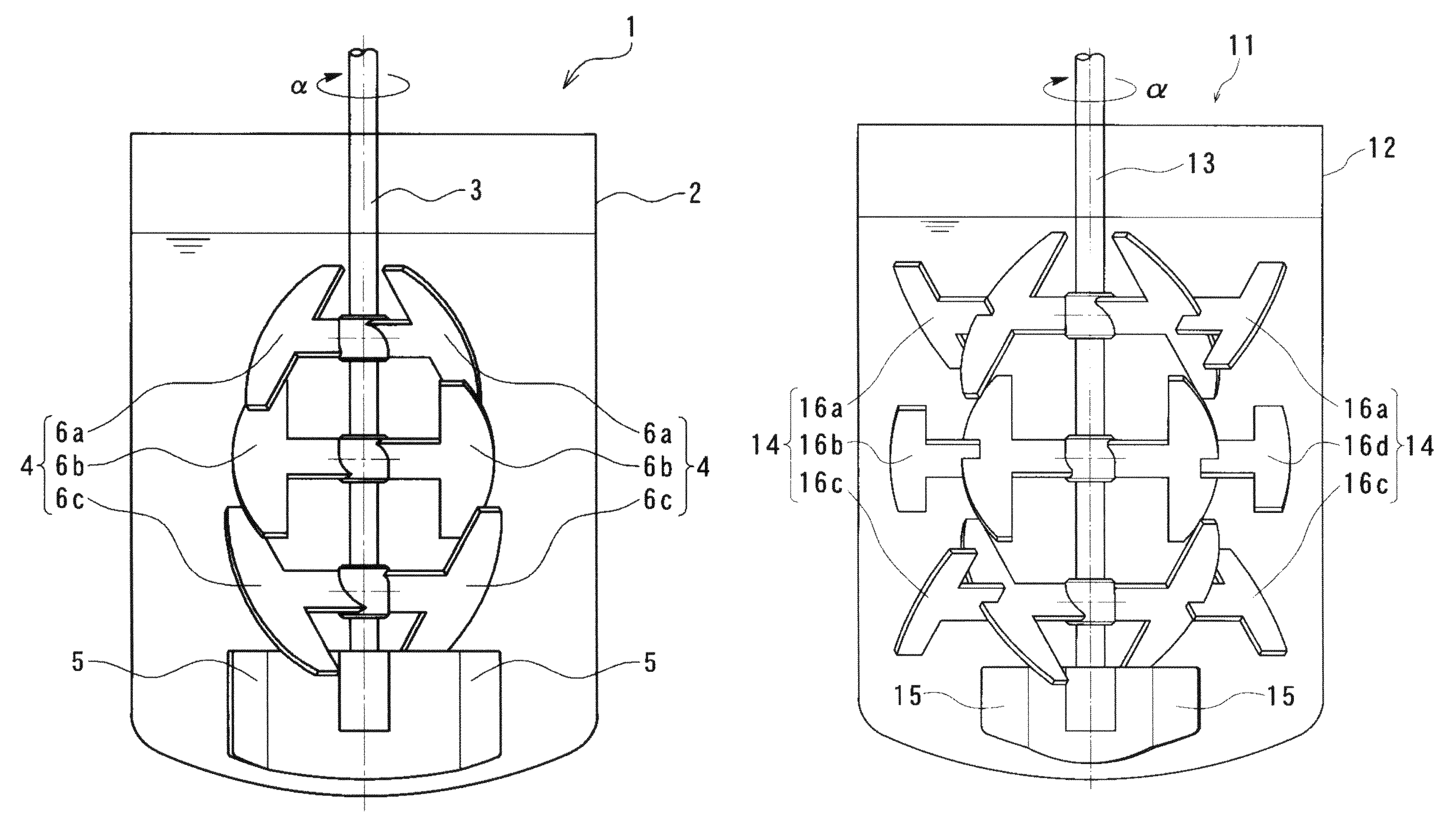
[0201]Using the agitation apparatus 11 of the present embodiment illustrated in FIGS. 4 to 6, the decoloration test was conducted using a solution of starch syrup under the same conditions as those of Example 2. The test was carried out with the number of rotation set to 90 rpm so that the agitation power was 1.5 kW / m3. As a result, the mixing completion time was 6.5 minutes.


PUM

PropertyMeasurementUnit
rotation angleaaaaaaaaaa
angleaaaaaaaaaa
elevation angleaaaaaaaaaa

Abstract

An agitation apparatus and an agitation method that ensure rapid and homogeneous agitation / mixing of fluids with a wide spectrum of viscosities from low to high levels and fluids with high thixotropy throughout an agitation vessel are provided. In an agitation apparatus, a lowest upper agitation blade is arranged to be vertically adjacent to a lower blade. As viewed from above, a line on a plane connecting a lower end portion of the lowest upper agitation blade to the center of an agitation shaft is arranged by a predetermined angle with respect to the center line of the lower blade in a blade radial direction. As viewed from the side, a horizontal cross section including the lower end portion of the lowest upper agitation blade is located below a horizontal cross section including an upper end portion of the lower blade.

Description

FIELD OF THE INVENTION[0001]The present invention relates to an agitation apparatus used in agitation processes for purposes such as mixing, dissolution, crystallization, reaction, distillation, defoaming, solvent removal, emulsification, and particulation.BACKGROUND OF THE INVENTION[0002]Conventionally, small-sized blades such as turbine blades, paddle blades, and propeller blades are often used as agitation blades of an agitation apparatus to process fluids with low to middle viscosities. To process fluids with middle to high viscosities, anchor blades or helical ribbon blades are often used as the agitation blades.[0003]However, it has been known that small-sized blades easily produce a flow boundary in an agitation vessel, which not only hampers generation of a vertically circulating flow throughout the vessel but also causes insufficient mixing when fluid with high viscosity is processed. Contrastingly, as has been known, the anchor blades or the ribbon blades cause insufficien...

Claims


Application Information

Patent Timeline
Patent Type & Authority Patents(United States)
IPC IPC(8): B01F7/20B01F27/906B01F23/47
CPCB01F7/00133B01F7/0015B01F7/00158B01F7/00633B01F7/18B01F7/00641Y10T29/49826B01F2215/0422B01F2215/0427B01F2215/0431B01F27/0723B01F27/0725B01F27/0726B01F27/192B01F27/191B01F27/90
Inventor HANDA, HARUHISA
Owner DAINIPPON INK & CHEM INC
Why Eureka
Try Eureka