Centrifugal separator and a liquid phase discharge port member

Active Publication Date: 2013-07-16
ALFA LAVAL CORP AB
View PDF18 Cites 15 Cited by
  • Summary
  • Abstract
  • Description
  • Claims
  • Application Information

AI Technical Summary

Benefits of technology

[0011]According to an embodiment of the invention the weir comprises a hole. The hole prevents liquid from flowing out of the bowl through the solid discharge opening during the start-up period by providing a liquid outlet effective at start-up conditions with a low feed rate to provide a low level of liquid in the bowl.
[0012]According to a preferred embodiment of the invention the weir is provided as an exchangeable weir plate, whereby the level of the overflow edge may be changed to correspond to the desired level of liquid in the bowl. According to a further preferred embodiment of the invention grooves are prov

Problems solved by technology

However in case a plurality of outlets with casings projecting from the base plate of the bowl is provided an angle of 0° m

Method used


Image

  • Centrifugal separator and a liquid phase discharge port member
  • Centrifugal separator and a liquid phase discharge port member
  • Centrifugal separator and a liquid phase discharge port member

Examples


Embodiment Construction

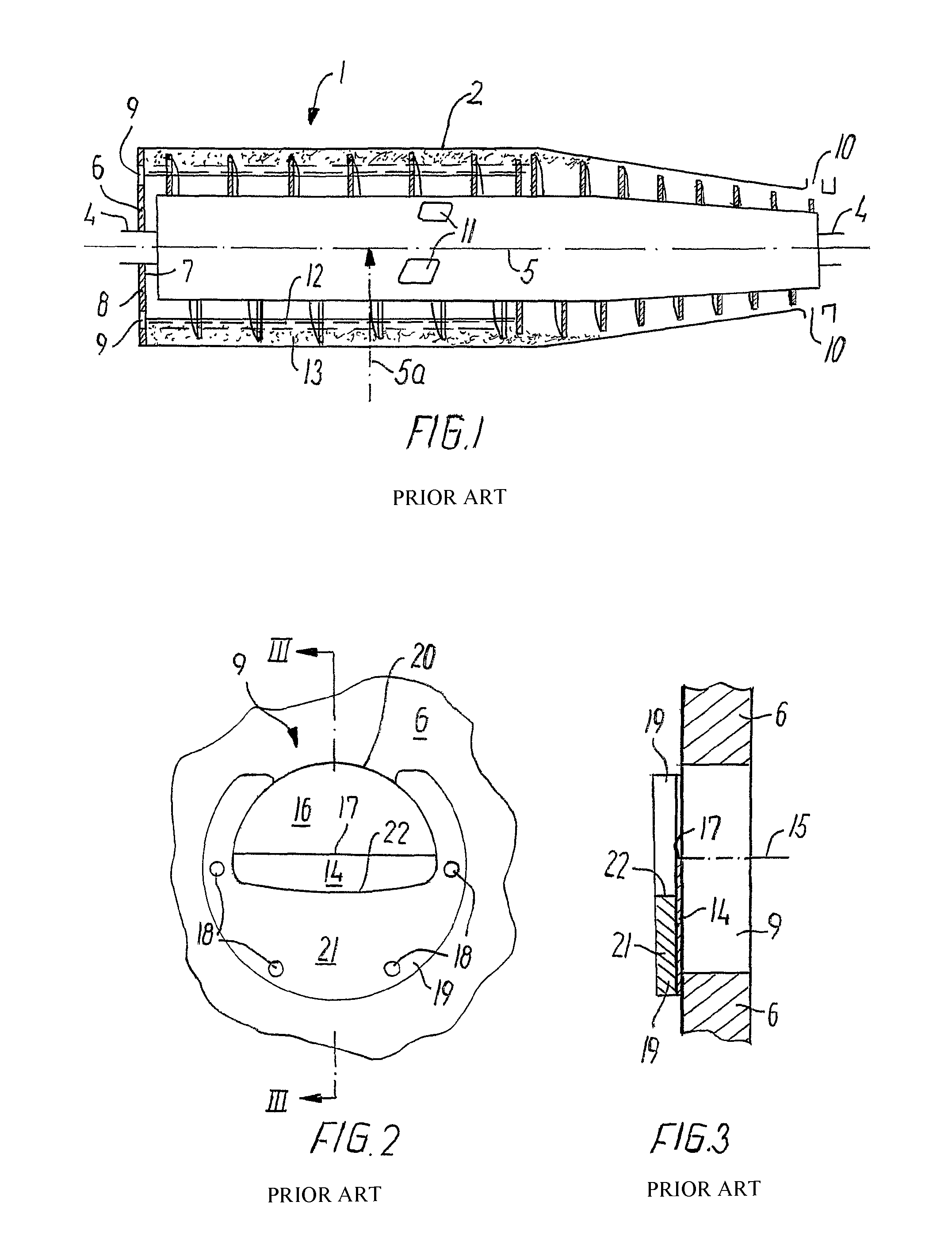
[0027]A prior art centrifugal separator 1 shown in FIG. 1 comprises a bowl 2 and a screw conveyor 3 which are mounted on a shaft 4 such that in use they can be brought to rotate around an axis 5, the axis of rotation 5 extending in a longitudinal direction of the bowl 2. Further, the centrifugal separator 1 has a radial direction 5a extending substantially perpendicular to the longitudinal direction.

[0028]For the sake of simplicity directions “up” and “down” are used herein as referring to a radial direction towards the axis of rotation 5 and away from the axis of rotation, respectively.

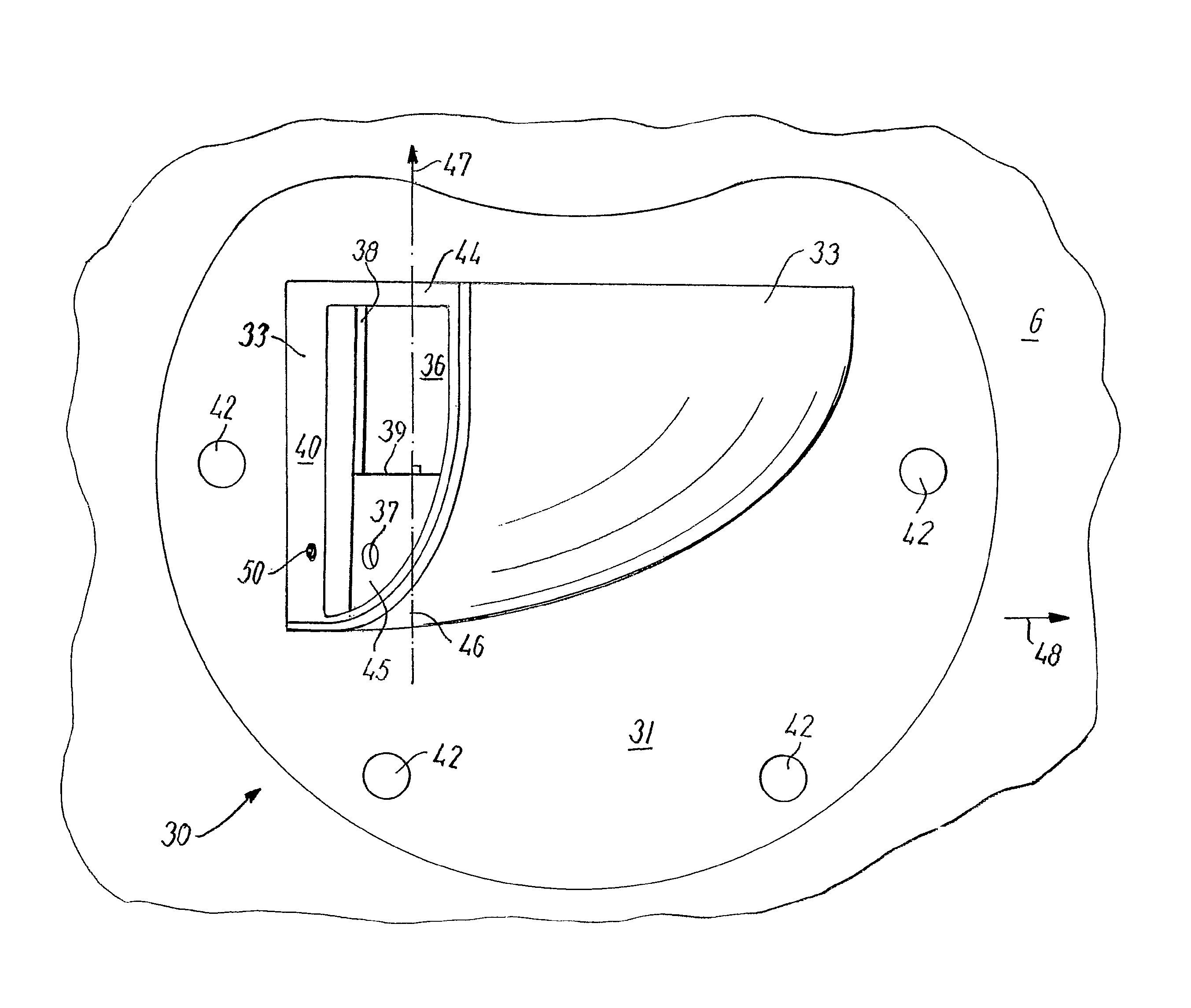
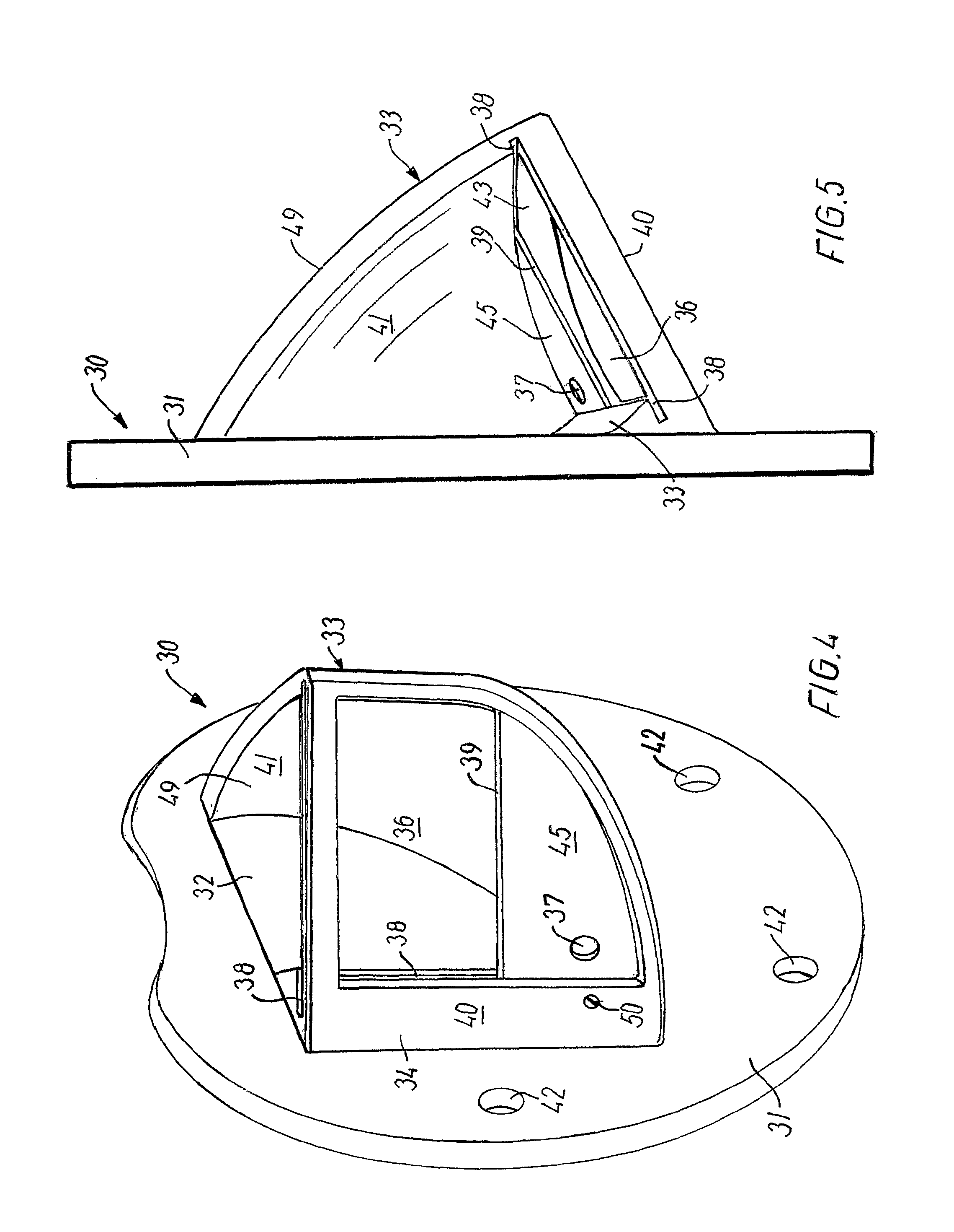
[0029]The bowl 2 comprises a base plate 6 provided at one longitudinal end of the bowl 2, which base plate 6 has an internal side 7 and an external side 8. The base plate 6 is provided with a number of liquid phase outlet openings 9. Furthermore the bowl 2 is at an end opposite to the base plate 6 provided with solid phase discharge openings 10.

[0030]Further the screw conveyor 3 comprises inlet openi...


PUM


Abstract

A centrifugal separator comprises a bowl rotating in use around an axis of rotation. The axis of rotation extends in a longitudinal direction, and a radial direction extends perpendicular to the longitudinal direction. A base plate provided at one longitudinal end of the bowl, said base plate having an internal and external side, an outlet opening being provided in the base plate. A casing is projecting at the outlet opening on the external side of said base plate, said casing comprising a casing side, a normal to said casing side extending at an acute angle relative to a circumferential direction of the bowl at said casing and a discharge opening is provided in said casing side. The discharge opening is radially outwardly limited by a weir with an overflow edge and said discharge opening extending radially inwardly to a position above a highest intended level of liquid in the bowl.

Description

FIELD OF THE INVENTION[0001]The present invention relates to a centrifugal separator comprising a bowl rotatable about an axis of rotation, said axis of rotation extending in a longitudinal direction of said bowl, a base plate provided at one longitudinal end of said bowl, said base plate having an internal side and an external side, an outlet opening provided in said base plate, a casing projecting at the outlet opening on the external side of said base plate, said casing comprising a casing side, a normal to said casing side extending at an acute angle to a circumferential direction of the bowl at said casing and a discharge opening being provided in said casing side.BACKGROUND OF THE INVENTION[0002]US 2004072668 describes a centrifugal separator having a casing with a nozzle provided in the casing side. Above the casing, i.e. closer the longitudinal axis, a weir may be provided. The depth of a pool of liquid in the bowl is determined by the diameter of the nozzle provided that th...

Claims


Application Information

Patent Timeline
IPC IPC(8): B04B11/02B04B1/20
CPCB04B1/20B04B11/00B04B2001/2083B04B2001/2075B04B1/14B04B11/02
Inventor MADSEN, BENTDIRCKS, KLAUS
Owner ALFA LAVAL CORP AB
Why Eureka
Try Eureka