Water deflection silt collection system

a collection system and water deflection technology, applied in water cleaning, filtration separation, separation processes, etc., can solve the problems of restricted water flow, roadway washouts or even landslides, water flowing through drainage ditches and streams can become contaminated with silt, etc., to reduce the amount of silt, and increase the effect of silt removal

Inactive Publication Date: 2013-07-16
BERGER JOHN
View PDF12 Cites 0 Cited by
  • Summary
  • Abstract
  • Description
  • Claims
  • Application Information

AI Technical Summary

Benefits of technology

[0005]In order to remove silt from flowing water, a water channel is selectively deepened by the creation of a recessed area below the bottom thereof. The recessed area is lined with a porous wrap, which is then filled with impervious objects. The wrap is then secured around the objects to hold them in place. The resultant trap slows the flow of water and permits some of the silt contained therein to settle to the bottom of the trap. The trap may then be periodically cleaned to maximize efficiency and collect the silt for use elsewhere. Multiple traps may also be employed to increase silt removal in a given water channel.

Problems solved by technology

Water flowing through channels such as drainage ditches and streams can become contaminated with silt—fine particles of sediment and organic material—from many sources.
Such disturbances expose soil to erosion and remove the natural vegetation which tends to slow down water flow.
Silt can be harmful to aquatic life, and also tends to accumulate in ways that result in restrictions in the flow of water.
This can lead to flooding, and in extreme cases, to roadway washouts or even landslides.
Parties responsible for the maintenance of environmental quality, as well as the safety of rural roads, face a dilemma: permitting the rapid flow of silt-laden water is preferable to avoid damming of water channels and the associated flooding, but on the other hand, healthy fisheries require clean water.
These dams slow water flow to permit settling, but results in large deposits of silt which must be laboriously removed from behind the dam.
Additionally, dams are problematic during periods of unusually high water flow.
Simple dams cannot accommodate this need, and instead lead to flooding if the dam is sturdy, or to dam failure if it is not, which releases the built up silt.

Method used


Image

  • Water deflection silt collection system
  • Water deflection silt collection system

Examples


Embodiment Construction

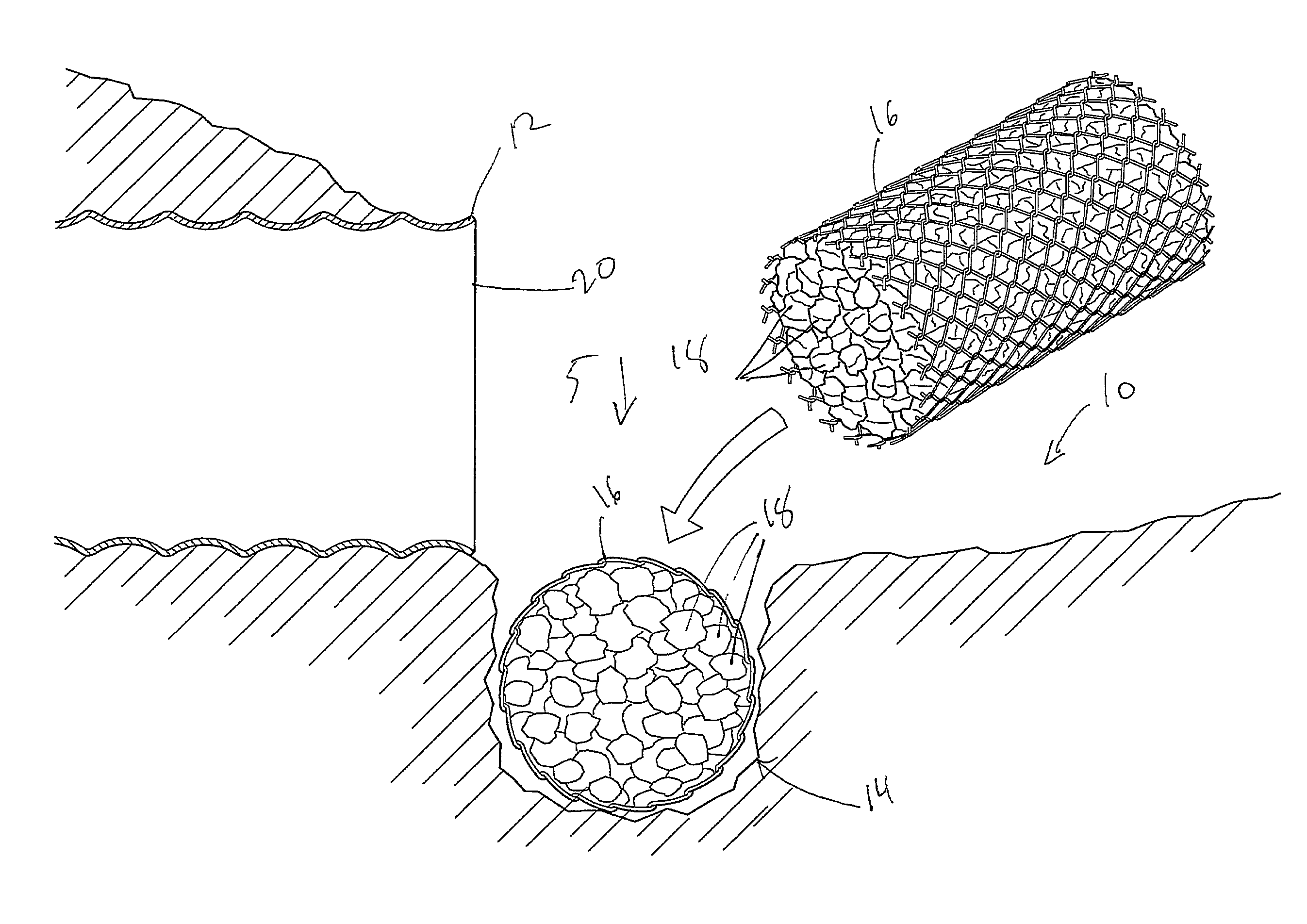
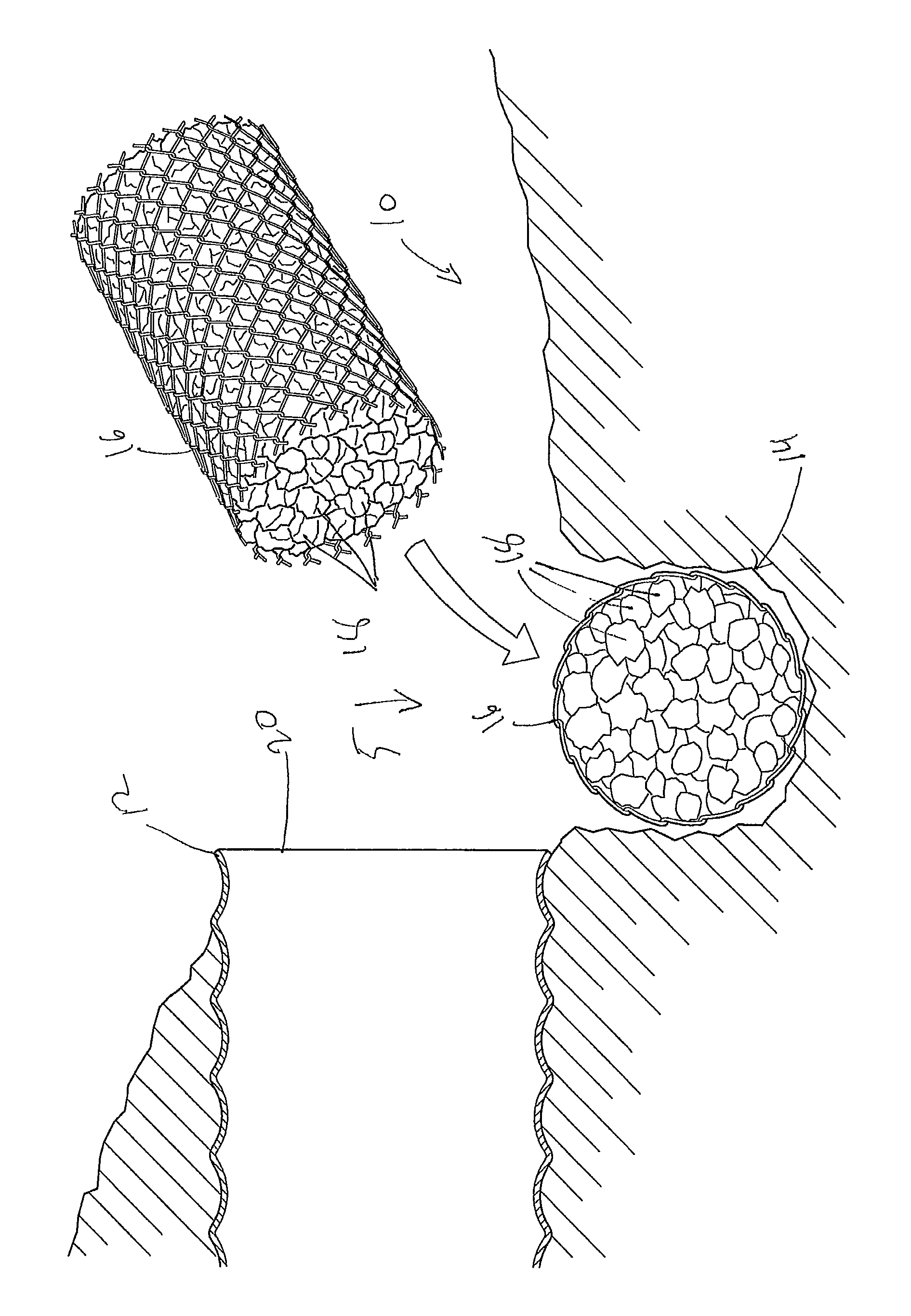
[0008]A “water channel” as used herein may be any place where water tends to flow in a concentrated manner, as opposed to a broad or sheet-like manner. Water channels need not carry water at all times, or even most of the time. The channel may be natural or artificial, and may carry water from natural sources, such as rain, or from artificial sources, such as irrigation, washing of equipment, construction sites, or residential, industrial, or agricultural effluent. Non-limiting examples of water channels include streams, irrigation and drainage ditches, swales, draws, culverts, French, tile, or perforated-pipe drains, and spillways.

[0009]A “substantially impervious object” as used herein is any object which absorbs minimal water when immersed in it, but need not be completely waterproof. They may be naturally occurring or artificial. Non-limiting examples include rocks, objects constructed of metal, fiberglass, plastic, or similar materials, and artificial rock-like objects such as ...


PUM

PropertyMeasurementUnit
diameteraaaaaaaaaa
diameteraaaaaaaaaa
diameteraaaaaaaaaa

Abstract

A device for removing silt from flowing water by temporarily slowing the water enough to permit silt to settle naturally to the bottom is disclosed. The water may be slowed by a combination of increased depth and obstructions in the form of rough rocks and chain link fencing.

Description

CROSS-REFERENCE TO RELATED APPLICATIONS[0001]This application claims the benefit of the filing date of U.S. Provisional Patent Application No. 61 / 318,185, filed Mar. 26, 2010, the entire disclosure of which is hereby incorporated herein by reference for all purposes.BACKGROUND[0002]Water flowing through channels such as drainage ditches and streams can become contaminated with silt—fine particles of sediment and organic material—from many sources. This is especially true when the channels are located in places of environmental disturbance, such as along roadways, near construction sites, and in agricultural areas. Such disturbances expose soil to erosion and remove the natural vegetation which tends to slow down water flow. Silt can be harmful to aquatic life, and also tends to accumulate in ways that result in restrictions in the flow of water. This can lead to flooding, and in extreme cases, to roadway washouts or even landslides.[0003]Parties responsible for the maintenance of en...

Claims


Application Information

Patent Timeline
Patent Type & Authority Patents(United States)
IPC IPC(8): B01D24/04E02B3/02E02B8/02E02B5/08
CPCE02B3/023E02B8/02B01D24/04E02B5/085E02B8/023Y02A10/00
Inventor BERGER, JOHN
Owner BERGER JOHN
Why Eureka
Try Eureka