Supercharge Your Innovation With Domain-Expert AI Agents!

Determination of the position of a component

a technology of component position and absolute position, applied in the field of determining the absolute position of a component, can solve the problems of increasing wear or damage to the flap or its drive, unable to diagnose, and unable to achieve the adjustment of the flap significantly longer, so as to prevent damage and premature wear, reliable position determination, and the effect of reliable

Inactive Publication Date: 2013-07-16
ROBERT BOSCH GMBH
View PDF10 Cites 0 Cited by
  • Summary
  • Abstract
  • Description
  • Claims
  • Application Information

AI Technical Summary

Benefits of technology

The object of this invention is to provide a way to determine the position of a component, like a flap used in an engine, without needing sensors. This method should be reliable and prevent damage and premature wear while still allowing for quick adjustments.

Problems solved by technology

If no external sensor is provided, no diagnosis can be performed.
This leads to increased wear or damage to the flap or to its drive.
However, the adjusting time of the flap becomes considerably longer, because of this.

Method used


Image

  • Determination of the position of a component
  • Determination of the position of a component

Examples


Embodiment Construction

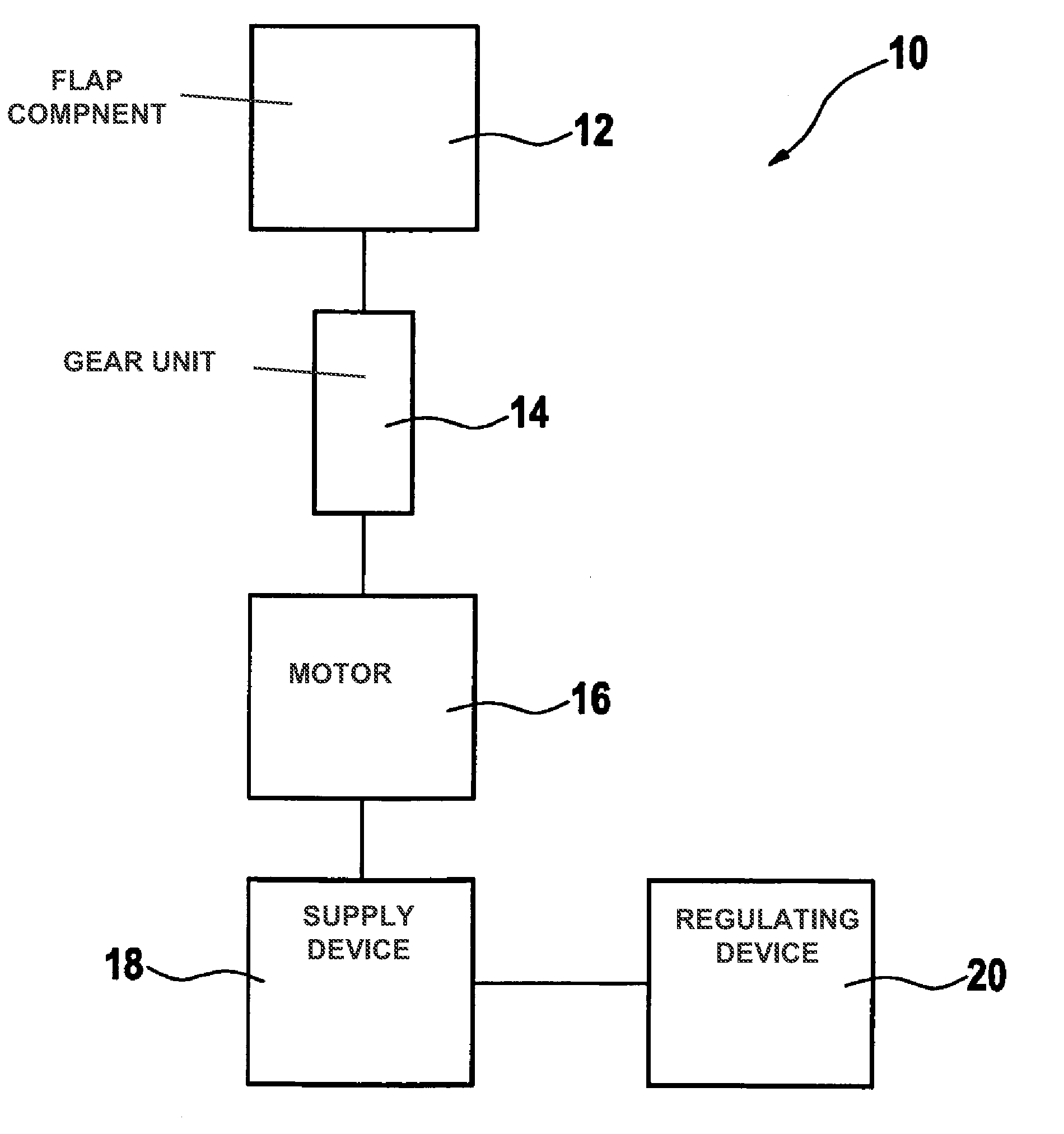
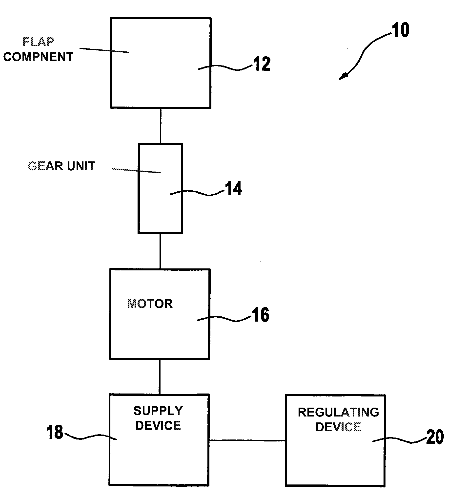
[0027]As may be seen in FIG. 1, a FIG. 10, for controlling fluid flows in an internal combustion engine according to a specific embodiment of the present invention, includes a component 12, which is coupled to a motor 16, such as a rotary DC motor, via a gear unit 14. The motor is driven with the aid of a current supply device 18 which, in turn, is connected to a position determining and regulating device 20.

[0028]Component 12 is a flap, for example, particularly a charge movement flap or an intake-manifold switchover flap which is movable back and forth between two end positions, or rather end stops. Such components 12 and their associated drives 14, 16 are known in principle for controlling fluid flows in an internal combustion engine, and are therefore not described here in greater detail.

[0029]During the operation of device 10, the rotational speed of motor 16 is first measured. This may be done by measuring an induced voltage when motor 16 has no energy supplied to it. The volt...


PUM


Abstract

A method for determining the position of a component, that is able to be moved into at least two end positions with the aid of a drive, especially of a flap for controlling fluid flows in an internal combustion engine, includes the following steps: providing an electric signal that indicates the speed of motion of an element of the drive, determining a change in position of the component by the integration of the electric signal, and determining the absolute position of the component from the change in position.

Description

BACKGROUND OF THE INVENTION[0001]1. Field of the Invention[0002]The present invention relates to a method and a device for determining the absolute position of a component, especially the absolute position of a flap for controlling fluid flows in an internal combustion engine.[0003]2. Description of Related Art[0004]Various flaps are provided in an internal combustion engine for controlling fluid flows. A charge movement flap may, for instance, be situated in the intake tract, shortly before the intake valve, in order to increase the turbulence of the flow in the combustion chamber, and thus to improve the thorough mixing of the air / fuel mixture. An intake-manifold switchover flap may also be provided, by which the effective length of an intake manifold is able to be changed. These flaps are usually driven by an electric motor and a gear unit, and are mostly just moved back and forth from end position to end position.[0005]Up to now, the position of such flaps has been either contro...

Claims


Application Information

Patent Timeline
Patent Type & Authority Patents(United States)
IPC IPC(8): H02P6/00
CPCF02D11/106F02D11/107F02D2200/0404Y10T137/7891
Inventor GROSSMANN, ALEXHALLOR, MATTIAS
Owner ROBERT BOSCH GMBH
Features
  • R&D
  • Intellectual Property
  • Life Sciences
  • Materials
  • Tech Scout
  • Unparalleled Data Quality
  • Higher Quality Content
  • 60% Fewer Hallucinations
Learn More