Zero degree grid antenna

a zero-degree grid antenna and antenna technology, applied in the direction of antennas, antenna feed intermediates, electrical devices, etc., can solve the problems of cable becoming part of the antenna, causing undesirable effects, and radiating normally undesirable patterns, and achieve the effect of reducing the effect of gain nulls

Inactive Publication Date: 2013-07-16
THE UNITED STATES OF AMERICA AS REPRESENTED BY THE SECRETARY OF THE NAVY
View PDF2 Cites 4 Cited by
  • Summary
  • Abstract
  • Description
  • Claims
  • Application Information

AI Technical Summary

Benefits of technology

[0045]Accordingly, it is an object of the present invention to provide a vertically polarized dipole or bicone antenna positioned cylindrically within many cylindrical layers of polarizing grids that slowly rotate the incident field to cross 0 degrees, i.e., 90 degrees ...

Problems solved by technology

Below cut-in, the bicone and similarly sized grids have high impedance and thus coupling to lower impedance longer cables going past the bicone is possible resultin...

Method used


Image

  • Zero degree grid antenna
  • Zero degree grid antenna
  • Zero degree grid antenna

Examples


Embodiment Construction

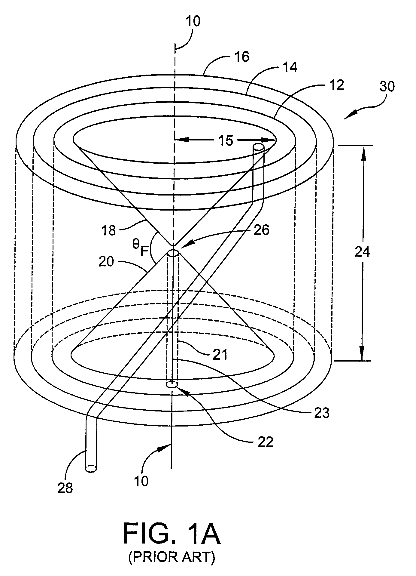
[0067]A possible mechanism for the creation of the cancellation nulls between the innermost layer of grids and the bicone is shown in FIGS. 5A, 5B. In FIG. 5A, a bicone 60 with an axis 62 is shown radially wrapped within the innermost layer 64 of grids. An incident wave 66 impinges on what is considered the front 68 of the grid layer 64, which typically is composed of a multitude of grids at a low pitch angle of 15 degrees.

[0068]The portion of the wave 66 which is passed by the grid continues to the bicone for reception. The wave 66 continues past the bicone 60 to the opposite side of the grids, considered to be the backside 70 of the innermost layer 64 of grids. At the backside 70, a significant part of the wave is reflected back (reflected wave 72) with the addition of 180 degrees of phase, since the backside direction of the grids is opposite to that of the front of the grids.

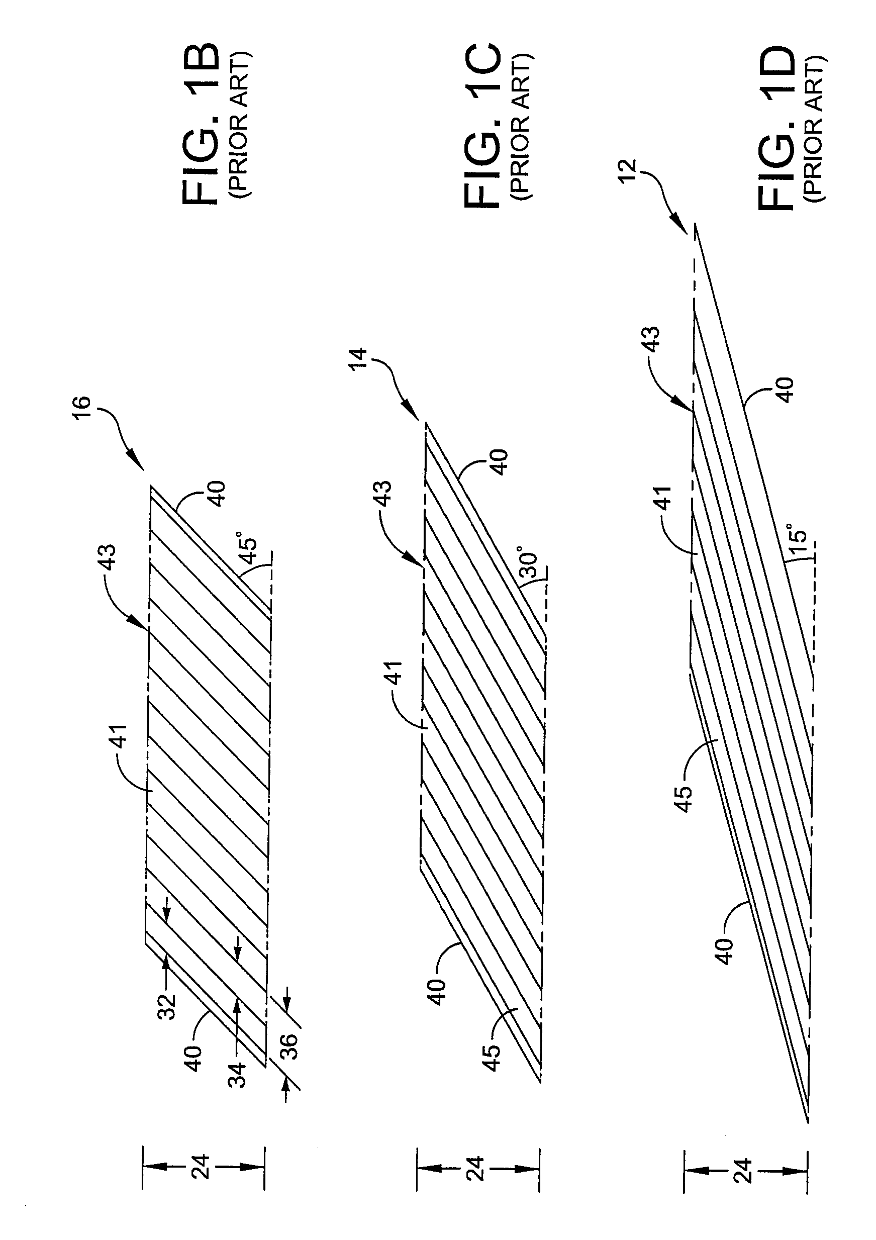
[0069]FIG. 5B illustrates the example of a 15 degree grid where if the front 68 of the grids is pitched 1...


PUM


Abstract

A vertically polarized dipole or bicone antenna is positioned cylindrically with in many cylindrical layers of polarizing grids that slowly rotate the incident field to cross 0 degrees, i.e., 90 degrees to the horizon, and to attenuate or minimize the effects of gain nulls from reflections off of the innermost grid layer. Such an antenna is used for detecting both horizontal and vertical polarized signals over a broad bandwidth whereby the response to both polarizations is equal.

Description

STATEMENT OF GOVERNMENT INTEREST[0001]The invention described herein may be manufactured and used by or for the Government of the United States of America for governmental purposes without the payment of any royalties thereon or therefore.CROSS REFERENCE TO OTHER PATENT APPLICATIONS[0002]This application is related to a patent application filed on the same day by the same inventor entitled CAPACITIVE LOADED GRID ANTENNA.BACKGROUND OF THE INVENTION[0003](1) Field of the Invention[0004]The present invention generally relates to vertically polarized RF antennas and more specifically to bicone and dipole antennas.[0005](2) Description of the Prior Art[0006]In the signal detection environment, it is often desirable to detect both horizontal and vertical polarized signals on the horizon over a broad bandwidth. It is also desirable that the response to both polarizations is equal. Optionally, an antenna may be used in a vertical stack of antennas, which requires cables to pass vertically b...

Claims


Application Information

Patent Timeline
IPC IPC(8): H01Q19/00H01Q13/00
CPCH01Q15/246H01Q9/28
Inventor JOSYPENKO, MICHAEL J.
Owner THE UNITED STATES OF AMERICA AS REPRESENTED BY THE SECRETARY OF THE NAVY
Why Eureka
Try Eureka