Digital peephole viewer device

a viewer device and peephole technology, applied in the field of digital peephole viewer devices, can solve the problems of inconvenience for users, user difficulty in recognizability of objects, and often too small lenses to provide sufficient vision field for users, so as to reduce fabrication costs and improve recognizability

Active Publication Date: 2013-07-16
BRINNO
View PDF3 Cites 6 Cited by
  • Summary
  • Abstract
  • Description
  • Claims
  • Application Information

AI Technical Summary

Benefits of technology

[0007]The primary objective of the present invention is to provide a digital peephole viewer device, which can integrate with a commercially-available door lens assembly without preparing any extra component of the door lens assembly for installation, and which utilizes a digital camera / display technology to provide better recognizability via instantly converting the external images into digital images and presenting the digital images on a larger monitor, whereby the user can watch the visitor and the external situation easily, and whereby the fabrication cost is reduced because the present invention does not need any new mold to fabricate additional components of the door lens assembly.
[0009]Another objective of the present invention is to provide a digital peephole viewer device, which has a modularized design, whereby the user can easily install the digital peephole viewer device to the existing door lens assembly.

Problems solved by technology

However, the lens is often too small to provide the user with a sufficient vision field.
Thus, the user is usually hard to recognize the object outside the door although he watches it attentively, which indeed inconveniences the user very much.
However, the conventional monitoring systems lack a modularized structure to facilitate convenient installation.
Most of the users cannot install a conventional monitoring system by themselves and must rely on professional personnel to install it.

Method used


Image

  • Digital peephole viewer device
  • Digital peephole viewer device
  • Digital peephole viewer device

Examples


first embodiment

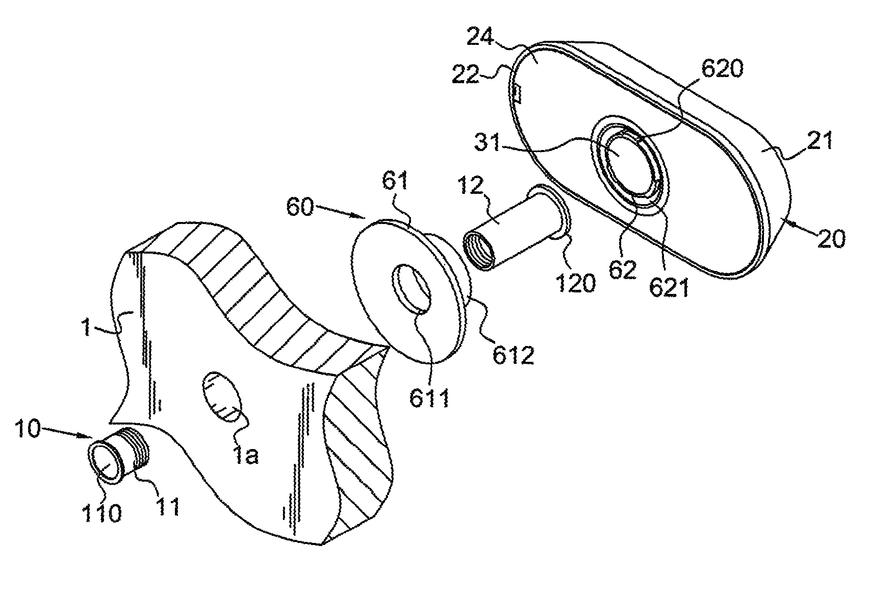
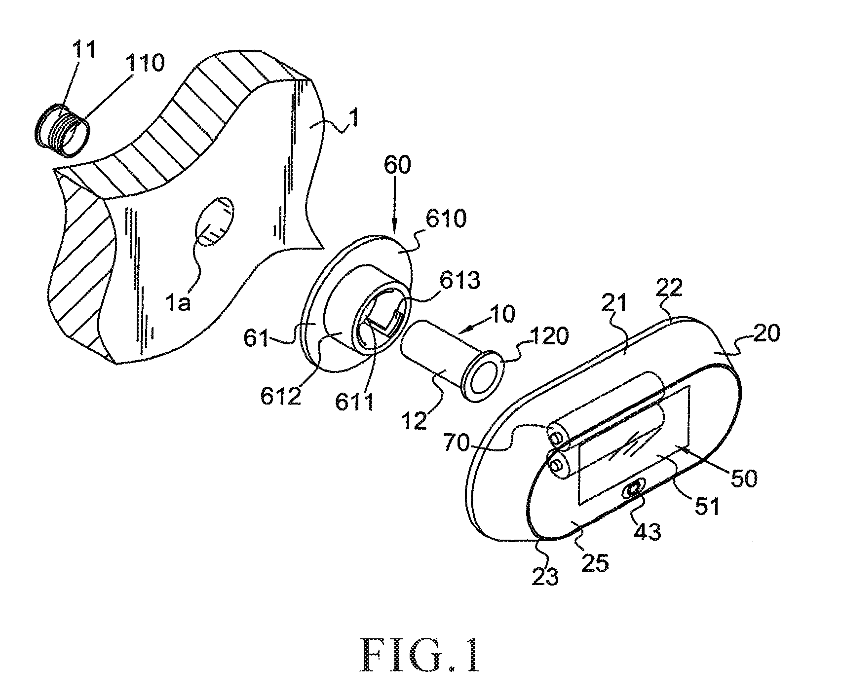
[0025]Refer to FIGS. 1-4. In the housing 20, the housing 20 includes a casing 21 having a first opening 22, and a cover 24 is used to cover the first opening 22. The casing 21 accommodates the power supply unit 70. The user can open the cover 24 to replace the power supply unit 70.

second embodiment

[0026]Refer to FIGS. 1-4. In the housing 20, the housing 20 includes a casing 21 having a second opening 23. The display 51 of the display unit 50 is installed in the second opening 23, and a transparent plate 25 is used to cover the second opening 23 and protect the display 51.

third embodiment

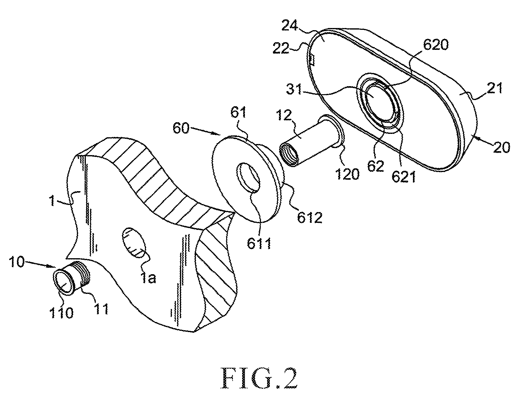
[0027]Refer to FIG. 1 and FIG. 2. In the housing 20, the housing 20 includes a casing 21 having a first opening 22 and a second opening 23. A cover 24 is used to cover the first opening 22. The casing 21 accommodates the power supply unit 70. The user can open the cover 24 to replace the power supply unit 70. The display 51 of the display unit 50 is installed in the second opening 23, and a transparent plate 25 is used to cover the second opening 23 and protect the display 51.

2.4 Image Capture Unit

[0028]Refer to FIG. 2, FIG. 7 and FIG. 8. The image capture unit 30 includes a first lens 31 arranged in the pipe 62 and a photosensor device 32, such as a CCD or CMOS device. Optical signals reach the photosensor device 32 via the light path of the second lens 110 of the door lens assembly 10 and the first lens 31. The photosensor device 32 converts the optical signals into an array of electronic signals. To achieve a better focusing effect, the axis of the door lens assembly 10 coincides...


PUM


Abstract

The present invention discloses a digital peephole viewer device, which integrates with a door lens assembly on a door board to acquire optical images captured by the door lens assembly, converts the optical images into digital images, and then presents the digital images. The digital peephole viewer device of the present invention comprises a housing, an image capture unit, a signal processing unit, a display unit and a connection means. The image capture unit has a first lens to receive the optical images captured by the door lens assembly. The signal processing unit converts the optical images into continuous dynamic digital images. The display unit presents the continuous dynamic digital images. The connection means integrates the housing with the door lens assembly.

Description

BACKGROUND OF THE INVENTION[0001]1. Field of the Invention[0002]The present invention relates to a digital peephole viewer device, particularly to a digital peephole viewer device, which comprises a housing, an image capture unit, a signal processing unit, a display unit and a connection means, and which can integrate with a door lens assembly to acquire optical images from the door lens assembly, and which transforms optical images into digital images and presents the images on the display unit, and which can further restore the distorted images and present the restored images.[0003]2. Description of the Related Art[0004]No matter whether a residence is in a townhouse, apartment or high-rise building, the door thereof usually has a door lens, whereby the host can watch the visitor or the event outside the house without opening the door.[0005]The conventional door lens assembly comprises a first tube and a second tube. The first tube has a lens. A first end of the second tube has an...

Claims


Application Information

Patent Timeline
Patent Type & Authority Patents(United States)
IPC IPC(8): H04N7/18
CPCE06B7/30H04N7/186A61P35/00
Inventor CHEN, SHIH-CHE
Owner BRINNO
Why Eureka
Try Eureka