Patient transfer kit

a patient and patient technology, applied in the field of patient transfer kits, can solve the problems of patient's body not being able to withstand the stress and strain of home, the challenge of moving a patient with minimal handling, and the inability of the patient's body to withstand the stress and strain of the hom

Active Publication Date: 2012-10-02
SAGE PRODS
View PDF47 Cites 25 Cited by
  • Summary
  • Abstract
  • Description
  • Claims
  • Application Information

AI Technical Summary

Problems solved by technology

Non-ambulatory patients who must be supported and moved in a patient facility such as a hospital or a nursing home present substantial challenges when a course of treatment for such patients calls for movement from one location to another.
In the case of a patient being returned to a hospital room following surgery, for example, the patient's body may not be able to withstand the stresses and strains of being lifted from a stretcher to the bed when one or even several hospital personnel combine their efforts to make such a transfer.
The same challenge of moving a patient with minimum handling exists in non-surgical settings as well.
When such a patient is morbidly obese, transferring presents difficulties for both the patient and the care facility staff.
The staff must perform the task of lifting and/or sliding such a patient because in nearly all instances the patient, due to the physical condition of obesity and/or illness, simply cannot personally do the task.
The manipulation of such a person requires a plurality of hospital staff since such manipulation is impossible to perform by a single person such as a floor nurse assigned to the patient's room.
Gathering together such a large number of people four times at often uncertain intervals to provide but a single cycle of treatment raises obvious logistical problems and, in addition, erodes the quality of care the facility can render by reason of the application of such a large number of personnel to deal with but a single patient treatment episode.
A further drawback to such a patient handling system as above described is that, even with the best intentioned and caring of staff, the patient very often suffers substantial discomfort.
The simple

Method used


Image

  • Patient transfer kit
  • Patient transfer kit
  • Patient transfer kit

Examples


Embodiment Construction

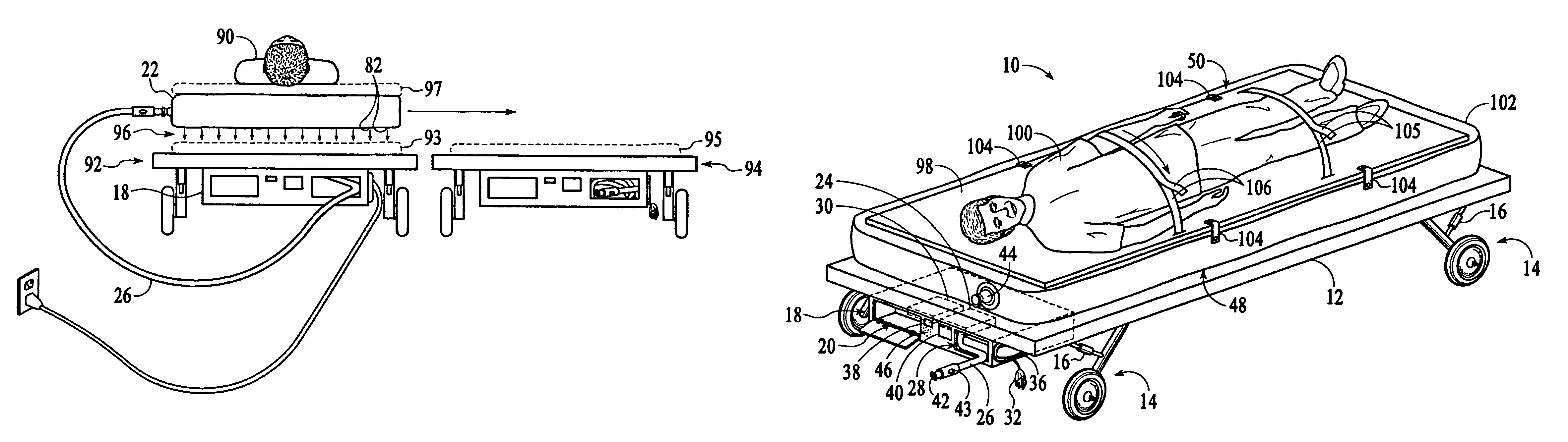
[0020]An embodiment of the system 10 of the present invention is shown in FIG. 1 as applied to a stretcher 12. The stretcher 12 can be of any type, such as used in a hospital or an ambulance, and can have fixed height legs 14 or adjustable height as indicated symbolically by adjusters 16. According to the system of the present invention, a patient bed illustrated as a stretcher 12 in FIG. 1 is assembled with an air mattress air supply system 18 attached. The term “air” as used in the present disclosure is meant to refer to air or any other gas that can be used to inflate an inflatable mattress. “Air mattress” therefore refers to a mattress that can be inflated with any such gas. Although the bed is illustrated as a stretcher, the present invention includes any type of bed / surface for supporting a patient, and will be referred to as a bed apparatus including any form of patient support, apparatus, such as a stretcher or hospital bed, etc. The supply system 18 has a compartment 20 for...


PUM


Abstract

A patient transfer kit including an inflatable mattress, alternatively with a rigid top board with a patient restraint system on which a patient can be placed, when patient immobilization is required. A portable cart is included with a chamber for storage of a plurality of mattresses. The cart also has a gas/air blower and power supply system for powering the blower. The power system includes provision for drawing power from line AC/DC, and has a rechargeable battery and charger for maintaining the battery by connecting the supply to the line AC/DC. The mattress has a perforated bottom surface for exit of air to provide an air cushion, and is constructed with a white top surface and a dark bottom surface for optimum recognition of contamination, and identification of the bottom surface which must be placed downward. The cart is coated with an antimicrobial substance to minimize the risk of contaminants.

Description

RELATED APPLICATIONS[0001]This application is a continuation-in-part of U.S. patent application Ser. No. 11 / 036,413 filed Jan. 15, 2005, now U.S. Pat. No. 7,114,204.FIELD OF THE INVENTION[0002]The present invention relates generally to apparatus for transferring bed patients, and more particularly to a system including a bed with an inflatable mattress for moving a patient on a cushion of air, wherein the bed has integrated thereon an assembly including a gas / air supply for inflating the mattress, and an air mattress storage container.BACKGROUND OF THE INVENTION[0003]Non-ambulatory patients who must be supported and moved in a patient facility such as a hospital or a nursing home present substantial challenges when a course of treatment for such patients calls for movement from one location to another. A patient, for example, may need to be moved from a hospital bed, which must remain in the patient's room, to a stretcher and then from the stretcher to a treatment location such as a...

Claims


Application Information

Patent Timeline
IPC IPC(8): A61G7/14A61G1/044
CPCA61G7/1046A61G7/1028A61G7/002A61G7/1021
Inventor PATRICK, JAMES E.
Owner SAGE PRODS
Why Eureka
Try Eureka