Ultrasound diagnosis apparatus and controlling method

A diagnostic device, ultrasonic technology, applied in the direction of acoustic wave diagnosis, infrasonic wave diagnosis, ultrasonic/sonic wave/infrasonic wave diagnosis, etc., which can solve the problems of image quality degradation, lower diagnostic ability, and suboptimal observation, etc., and achieve the effect of improving recognition

Active Publication Date: 2012-10-17
TOSHIBA MEDICAL SYST CORP
View PDF5 Cites 25 Cited by
  • Summary
  • Abstract
  • Description
  • Claims
  • Application Information

AI Technical Summary

Problems solved by technology

[0005] Among them, the image quality of living tissue drawn in an ultrasonic image generated by oblique scanning is degraded due to the influence of side lobes, etc., compared with that of a non-oblique scan.
Therefore, even if the visibility of the puncture needle in the synthesized image is somewhat improved, the observation of the nature of the tissue lesion is n

Method used


Image

  • Ultrasound diagnosis apparatus and controlling method
  • Ultrasound diagnosis apparatus and controlling method
  • Ultrasound diagnosis apparatus and controlling method

Examples


Example

[0023] (First embodiment)

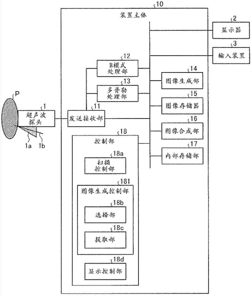
[0024] First, the configuration of the ultrasonic diagnostic apparatus according to the first embodiment will be described. figure 1 It is a figure for demonstrating the structure of the ultrasonic diagnostic apparatus concerning 1st Embodiment. Such as figure 1 As shown, the ultrasonic diagnostic apparatus according to the first embodiment includes an ultrasonic probe 1, a monitor 2, an input device 3, and an apparatus main body 10.

[0025] The ultrasonic probe 1 is detachably connected to the device main body 10. The ultrasonic probe 1 has a plurality of piezoelectric vibrators, and these plurality of piezoelectric vibrators generate ultrasonic waves in accordance with a drive signal supplied from a transmission and reception unit 11 included in the apparatus main body 10 described later. In addition, the ultrasonic probe 1 receives the reflected wave from the subject P and converts it into an electric signal. In addition, the ultrasonic probe 1 has...

Example

[0082] (Second embodiment)

[0083] In the second embodiment, for the case where the third ultrasound image selection process is executed after the brightness adjustment of the second ultrasound image group, Figure 7 And so on. Figure 7 It is a figure for demonstrating the structure of the control part concerning 2nd Embodiment.

[0084] Such as Figure 7 As shown, the control unit 18 according to the second embodiment and figure 1 Compared with the control unit 18 according to the first embodiment shown, the difference lies in that it further includes an adjustment unit 18e. Hereinafter, the description will focus on this. In addition, as in the first embodiment, even in the second embodiment, after the first scan and the second scan are performed, the first ultrasound image and the second ultrasound image group are generated.

[0085] Here, if the ultrasound beam is tilted, the brightness of the entire image becomes higher due to the influence of side lobes, or the image quality...

Example

[0097] (Third Embodiment)

[0098] In the third embodiment, a case where the third ultrasonic image selection process is executed after image processing using the first ultrasonic image is performed on the second ultrasonic image group will be described.

[0099] The control unit 18 and use of the third embodiment figure 1 The control unit 18 according to the first embodiment described is similarly configured. However, in the third embodiment, the processing of the selection unit 18b included in the image control unit 181 is different from the first embodiment and the second embodiment. Hereinafter, the description will focus on this. In addition, even in the third embodiment, as in the first and second embodiments, after the first scan and the second scan are performed, the first ultrasound image and the second ultrasound image group are generated.

[0100] The image generation control unit 181 according to the third embodiment controls the image generation unit 14 to generate a h...


PUM


Abstract

Embodiments relate to ultrasound diagnosis apparatus and a controlling method, which can improve recognizability of both tissues of living organisms and punture needles . The ultrasound diagnosis apparatus includes: a scan controlling unit that exercises control to perform a first scanning process by transmitting an ultrasound wave in a first direction and a second scanning process by transmitting an ultrasound wave in each of a plurality of directions; an image generating unit that generates a first ultrasound image and second ultrasound images from the first and the second scanning processes, respectively; an image generation controlling unit that has a needle image generated, based on an analysis result on the brightness distribution of each member of a group of images based on the first ultrasound image and the second ultrasound images or an analysis result on the brightness distribution of each of the second ultrasound images; an image synthesizing unit that generates a synthesized image from the first ultrasound image and the needle image; and a display controlling unit that displays the synthesized image.

Description

[0001] This application claims the priority of Japanese Patent Application No. 2011-081986 filed on April 1, 2011 and Japanese Patent Application No. 2012-41505 filed on February 28, 2012, and all of the aforementioned Japanese Patent Applications are cited in this application content. technical field [0002] Embodiments relate to an ultrasonic diagnostic apparatus and a control method. Background technique [0003] Conventionally, ultrasonic diagnostic equipment has been frequently used in biological tissue examinations and radio frequency therapy (RFA: Radio Frequency Ablation), etc. The case of a puncture. However, depending on the position of the lesion or the insertion angle of the puncture needle, it may be difficult to see the puncture needle. In this case, the puncture is performed while observing the movement of the tissue when the puncture needle is moved. [0004] Therefore, in recent years, in order to improve the visibility of the puncture needle during punct...

Claims


Application Information

Patent Timeline
IPC IPC(8): A61B8/00
CPCA61B8/00A61B8/488A61B8/5246A61B8/486A61B8/46A61B8/0841A61B8/5238A61B2017/3413
Inventor 冈村阳子神山直久
Owner TOSHIBA MEDICAL SYST CORP
Why Eureka
Try Eureka