Method for measuring lateral movements in a driver assistance system

Active Publication Date: 2009-06-18
ROBERT BOSCH GMBH
View PDF15 Cites 25 Cited by
  • Summary
  • Abstract
  • Description
  • Claims
  • Application Information

AI Technical Summary

Benefits of technology

[0009]An object of the present invention is to provide a method for driver assistance systems, which allows rapid and pre

Problems solved by technology

Because of the limited angle resolution capability, the precision when determining the lateral position (y position) of the object is significantly worse, however, than the precision when determining the distance.
A direct measurement of the transverse component of the velocity of the object is not possible.
The unavoidable inaccuracies in the measurement of the lateral position of the object are reinforced

Method used


Image

  • Method for measuring lateral movements in a driver assistance system
  • Method for measuring lateral movements in a driver assistance system
  • Method for measuring lateral movements in a driver assistance system

Examples


Embodiment Construction

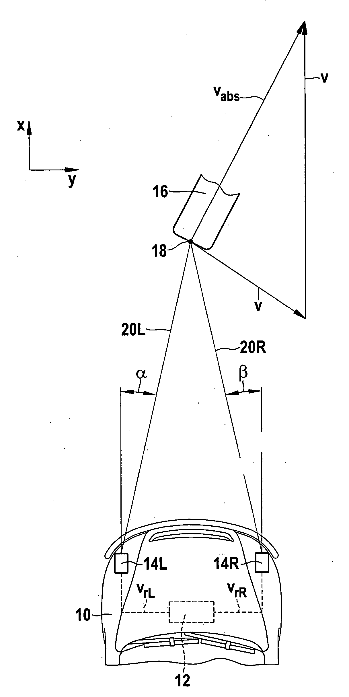
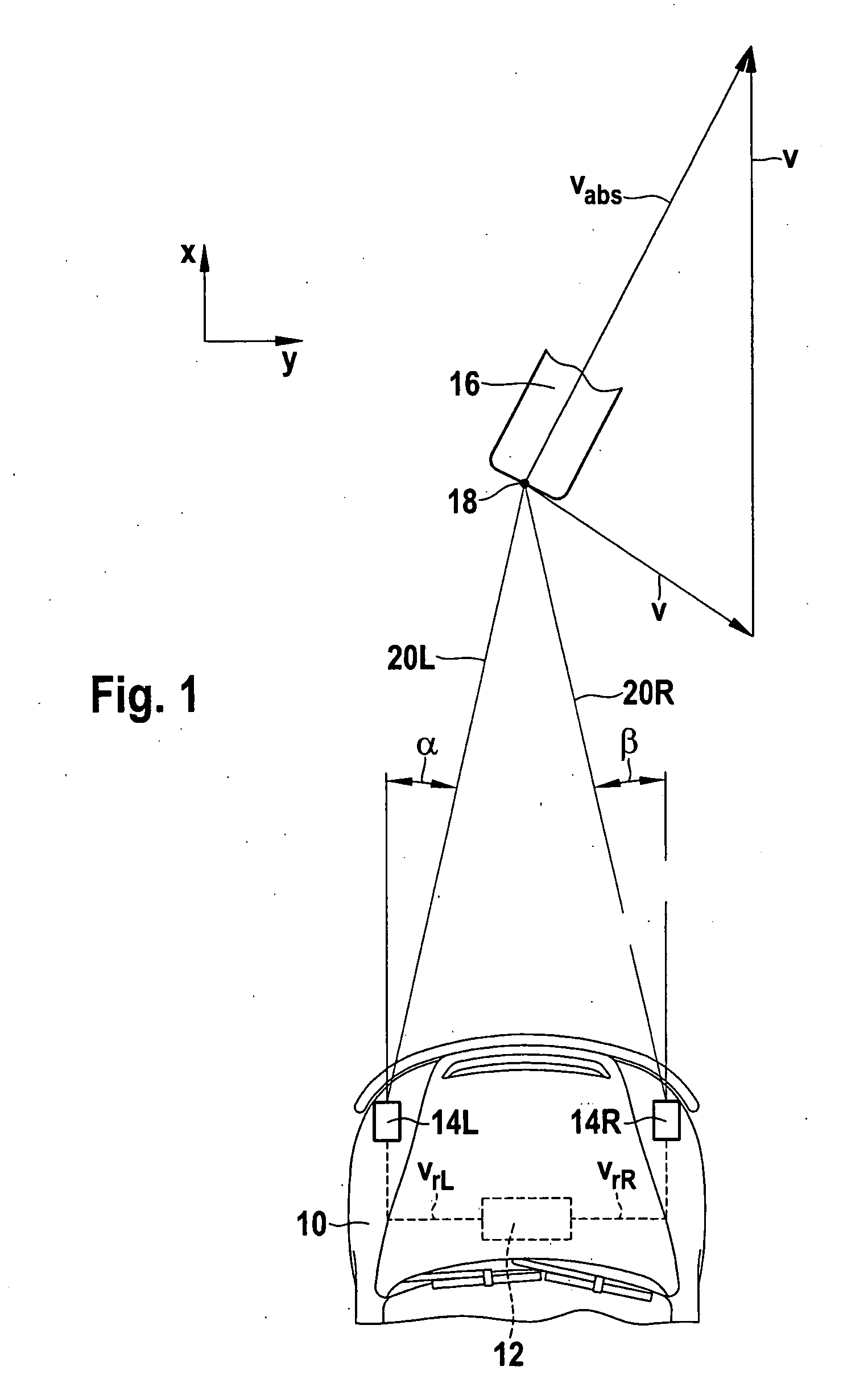
[0025]FIG. 1 schematically shows the front part of a motor vehicle 10, which is equipped with a driver assistance system 12, such as an ACC system. This driver assistance system includes two angle-resolving distance sensors 14L and 14R, which are installed in proximity to the left and right lateral delimitations of vehicle 10 in the front part, so that they jointly monitor the area in front of vehicle 10. For example, distance sensors 14L and 14R are long-range radar sensors (LRR).

[0026]In the example shown, an approximately punctiform object 16, such as the rear end of a preceding motorcycle, is located by both distance sensors 14L and 14R. It may be assumed as a somewhat idealized case that both sensors receive radar echoes from a single reflection point 18 on the rear of object 16. Accordingly, left distance sensor 14L measures the value for the distance between reflection point 18 and this distance sensor and a value for radial component vrL of the relative velocity of object 16...


PUM


Abstract

Method for determining a dynamic variable representative for a lateral movement of a located object in a driver assistance system for motor vehicles, which has two angle-resolving distance sensors situated laterally offset to one another for locating the object, using which a radial component of the relative velocity of the object along the particular line of sight is also measurable, wherein the dynamic variable is calculated on the basis of the radial components of the relative velocity measured by the two distance sensors.

Description

FIELD OF THE INVENTION[0001]The present invention relates to a method for determining a dynamic variable representative for a lateral movement of a located object in a driver assistance system for motor vehicles, which has two angle-resolving distance sensors situated laterally offset to one another for locating the object, using which a radial component of the relative velocity of the object along the particular line of sight is also measurable.BACKGROUND INFORMATION[0002]Examples of driver assistance systems in which the present invention is used are, for example, so-called ACC systems (adaptive cruise control), which allow an automatic regulation of the distance to a preceding vehicle (the object), as well as predictive safety systems (PSS), which are used for automatically recognizing an imminent collision, so that measures for avoiding the collision or for mitigating the collision consequences may be initiated.[0003]Precise knowledge of the lateral movements of the object is si...

Claims


Application Information

Patent Timeline
IPC IPC(8): G08G1/00G01S13/931
CPCB60W40/04G01S13/589G01S13/878G01S2013/9375G01S2013/9321G01S2013/9325G01S13/931G01S2013/93271
Inventor JORDAN, RUEDIGERSCHWINDT, OLIVER
Owner ROBERT BOSCH GMBH
Why Eureka
Try Eureka