Projection screen and projection system comprising the same

a projection screen and projection system technology, applied in the field of projection systems, can solve the problems of inability to provide good image display performance, inability to meet inability to achieve the effect of satisfying the requirements of the above-described conventional projection screen, reducing the brightness of the dark-indication part, and improving light reflection efficiency

Inactive Publication Date: 2005-02-10
DAI NIPPON PRINTING CO LTD
View PDF6 Cites 29 Cited by
  • Summary
  • Abstract
  • Description
  • Claims
  • Application Information

AI Technical Summary

Benefits of technology

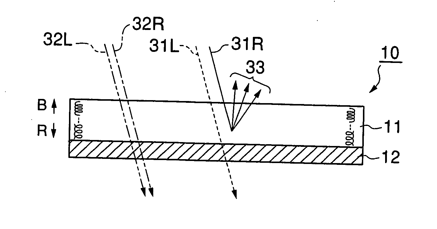
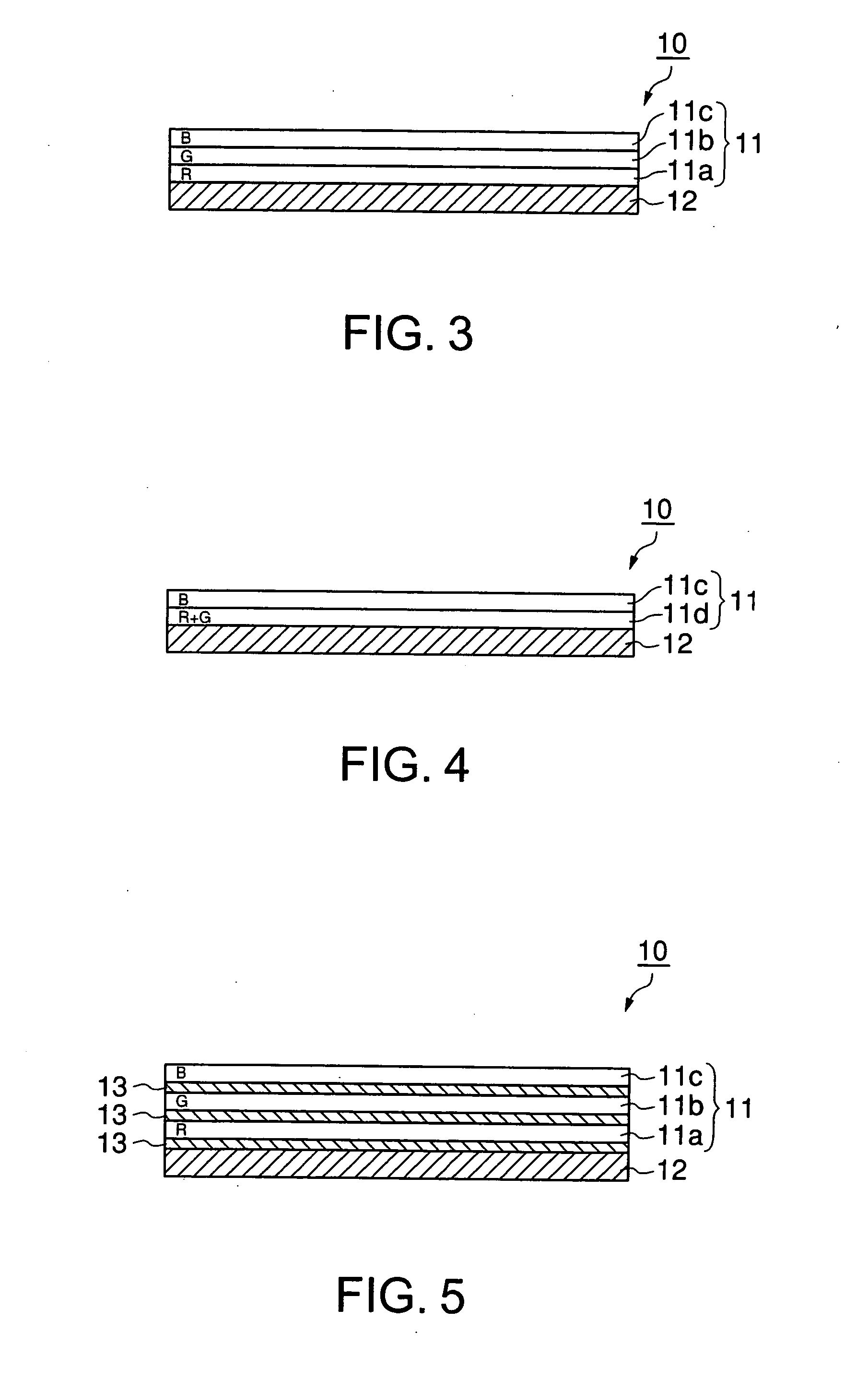
According to the present invention, the polarized-light selective reflection layer has a periodic structure in which layers that are anisotropic with respect to refractive index and selectively reflect a specific polarized-light component are layered in the direction of thickness, and, in the polarized-light selective reflection layer, the periodic optical pitch on the side farther from the imaging-light-incident side is made longer than that on the side closer to the imaging-light-incident side. When light is slantingly incident on the polarized-light selective reflection layer having such a periodic structure, phase differences are produced, and, for example, circularly polarized light is converted into elliptically polarized light. However, the polarized-light selective reflection layer reflects, owing to its periodic structure, the converted elliptically polarized light at decreased reflectance, which causes the loss of light. In the present invention, a layer having a shorter periodic optical pitch, capable of attaining nearly 100% of reflectance even if it is thin, is provided on the viewer's side as compared with a layer having a longer periodic optical pitch. Therefore, the influence of phase differences that are produced in proportion to the thickness of the periodic structure (the influence of the layer situated on the side closer to the viewer's side exerted on the layer situated on the side farther from the viewer's side) can be minimized, and the light reflection efficiency can thus be improved, as a whole. As a result, the projection screen can sharply display an image.
Further, according to the present invention, the polarized-light selective reflection layer selectively reflects only a specific polarized-light component (e.g., right-handed circularly polarized light), so that this layer can be made to reflect only approximately 50% of the unpolarized environmental light such as sunlight and light from lighting fixtures that are incident on this layer. For this reason, while maintaining the brightness of the light-indication part such as a white-indication part, it is possible to lower the brightness of the dark-indication part such as a black-indication part to nearly half, thereby obtaining nearly twice-enhanced image contrast. In this case, if the imaging light to be projected is made to mainly contain a polarized-light component that is identical with the polarized-light component which the polarized-light selective reflection layer selectively reflects (e.g., right-handed circularly polarized light), the polarized-light selective reflection layer can reflect nearly 100% of the imaging light projected on this layer, that is, this layer can efficiently reflect the imaging light.
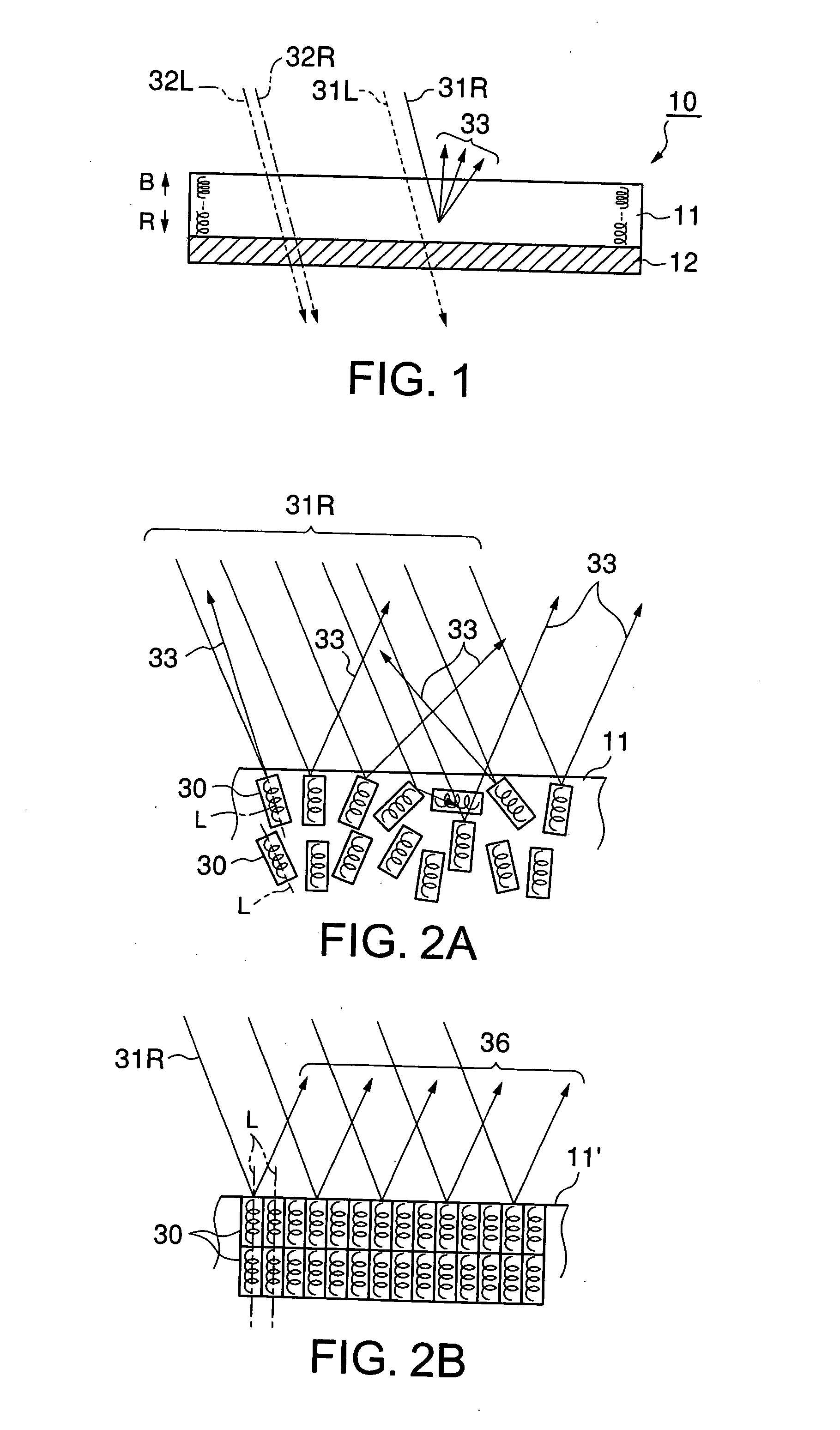
Furthermore, according to the present invention, if the polarized-light selective reflection layer is made to have, as the periodic structure, a cholesteric liquid crystalline structure, and this cholesteric liquid crystalline structure is made structurally non-uniform (for example, the helical-structure parts of the cholesteric liquid crystalline structure have helical axes extending in different directions), the polarized-light selective reflection layer reflects imaging light not by specular reflection but by diffuse reflection, and the reflected light can thus be well recognized as an image. At this time, owing to structural non-uniformity in the cholesteric liquid crystalline structure, the polarized-light selective reflection layer diffuses light that is selectively reflected. The polarized-light selective reflection layer can, therefore, reflect a specific polarized-light component while diffusing it, and, at the same time, transmit the other light components without diffusing them. For this reason, the environmental light and imaging light that pass through the polarized-light selective reflection layer do not undergo so-called depolarization, that is, the disturbance of the state of polarization, and it is thus possible to improve image visibility while maintaining the polarized-light-separating property inherent in the polarized-light selective reflection layer.

Problems solved by technology

However, the above-described conventional projection screens cannot show good image display performance under bright environmental light because they reflect not only imaging light but also environmental light such as sunlight and light from lighting fixtures.
However, since the above-described conventional projection screen reflects both imaging light and environmental light such as sunlight and light from lighting fixtures without distinction, both the white- and black-indication parts get lighter, and differences in brightness between white and black become small.
For this reason, the conventional projection screen cannot satisfactorily provide good image display unless the influence of environmental light such as sunlight and light from lighting fixtures on the projection screen is suppressed by using a means for shading a room, or by placing the projection screen in a dark environment.
However, holograms have wavelength selectivity but no polarization selectivity, so that the projection screens using holograms can display images only with limited sharpness.
Moreover, it is difficult to produce large-sized projection screens by utilizing holograms because of production problems.

Method used


Image

  • Projection screen and projection system comprising the same
  • Projection screen and projection system comprising the same
  • Projection screen and projection system comprising the same

Examples


examples

The present invention will now be explained more specifically by referring to the following Example and Comparative Example.

example

A first cholesteric liquid crystal solution having a selective reflection wave range with a center wavelength of 600 nm was prepared by dissolving, in cyclohexanone, a monomer-containing liquid crystal consisting of a main component (97% by weight), an ultraviolet-curing nematic liquid crystal, and a polymerizable chiral agent (3% by weight). A liquid crystal containing a compound represented by the above chemical formula (2-xi) was used as the nematic liquid crystal. A compound represented by the above chemical formula (5) was used as the polymerizable chiral agent. To the first cholesteric liquid crystal solution was added 5% by weight of an acetophenone photopolymerization initiator available from Ciba Specialty Chemicals K.K., Japan.

By a bar coating method, the above-prepared first cholesteric liquid crystal solution was applied to a black-colored acrylic sheet with a surface area of 200 mm□(200 mm×200 mm).

This acrylic sheet was heated in an oven at 80° C. for 90 seconds, t...


PUM


Abstract

The present invention provides a projection screen capable of sharply displaying an image by minimizing the influence of phase differences that are produced when light is slantingly incident on a polarized-light selective reflection layer having a cholesteric liquid crystalline structure, and of providing high image visibility. A projection screen includes: a polarized-light selective reflection layer having a cholesteric liquid crystalline structure, capable of selectively reflecting a specific polarized-light component; and a substrate that supports the polarized-light selective reflection layer. The cholesteric liquid crystalline structure of the polarized-light selective reflection layer contains a plurality of helical-structure parts that are different in direction of helical axis, and, owing to structural non-uniformity in the cholesteric liquid crystalline structure, the polarized-light selective reflection layer diffuses light (imaging light) that is selectively reflected. In the cholesteric liquid crystalline structure of the polarized-light selective reflection layer, the helical pitch on the side farther from the imaging-light-incident side is longer than that on the side closer to the imaging-light-incident side.

Description

BACKGROUND OF THE INVENTION 1. Field of the Invention The present invention relates to a projection system in which imaging light emitted from a projector is projected on a projection screen to display thereon an image. More particularly, the present invention relates to a projection screen capable of sharply displaying an image and of providing high image visibility, and to a projection system comprising such a projection screen. 2. Background Art A conventional projection system is usually as follows: imaging light emitted from a projector is projected on a projection screen, and viewers observe the light reflected from the projection screen as an image. Typical examples of projection screens for use in such conventional projection systems include white-colored paper or cloth materials, and plastic films coated with inks that scatter white light. Besides, high-quality projection screens that comprise scattering layers containing beads, pearlescent pigments, or the like, capab...

Claims


Application Information

Patent Timeline
Patent Type & Authority Applications(United States)
IPC IPC(8): G03B21/56
CPCG03B21/56
Inventor UMEYA, MASANORI
Owner DAI NIPPON PRINTING CO LTD
Why Eureka
Try Eureka