Railroad rail having thermal insulation below the railhead either coated in the field or at the rail production facility

a technology of thermal insulation and railhead, which is applied in the field of railhead thermal insulation, can solve the problems of loosing the ballast around the ties, serious injuries or even deaths, and the number of serious injuries or even deaths, and achieves the effects of cost saving, and decreasing the thermal expansion of the rail

Inactive Publication Date: 2013-07-23
JONES PAUL
View PDF2 Cites 19 Cited by
  • Summary
  • Abstract
  • Description
  • Claims
  • Application Information

AI Technical Summary

Benefits of technology

[0018]It is, therefore, one of the primary objects of the present invention to provide a method of decreasing the thermal expansion of a rail.
[0019]Another object of the present invention is to provide a method of decreasing the thermal expansion of a rail which will be cost effective due to a reduction in the cost of maintaining the track.
[0020]Still another object of the present invention is to provide a method of decreasing the thermal expansion of a rail which can potentially provide fewer derailments caused by buckling of a rail and the cost associated therewith.
[0021]Yet another object of the present invention is to provide a method of decreasing the thermal expansion of a rail which can be retrofitted to rail already disposed in a track structure.
[0022]An additional object of the present invention is to provide a method of decreasing the thermal expansion of a rail which can be accomplished while a track in still in service.
[0023]A further object of the present invention is to provide a rail having an improved capability to resist thermal expansion and thereby resist buckling during service.

Problems solved by technology

Such buckling can cause a number of difficulties not the least of which is derailment of a train running of such rails.
These derailments are not only costly to the railroads due to equipment damage but also such derailments can cause a number of serious injuries or even death, as for example, when such derailment involves a passenger train.
As has been reported, track buckling is formation of large lateral misalignments in continuous welded rail (CWR) track, often resulting in catastrophic these derailments.
Another significant problem that can be attributed to such rail expansion is that it will oftentimes cause the railroad ties supporting the rails to shift and thereby loosen the ballast around the ties.
The shifting of ties can also contribute to derailments and will at least add significantly to the cost of maintaining the track bed in a serviceable condition.
Weakened track conditions impacting the tracks buckling potential include: reduced track Resistance, lateral alignment defects, and lowered rail neutral temperature.
Ballast on the low side is important because inward (pulling-in) movement in cold weather could lead to line defects and lowering of neutral temperature which could lead to a buckle when higher temperature rises occur in early spring.
Lateral alignment defects also reduce the track's buckling strength because buckles tend to initiate at alignment deviations.
The larger the line defect, the more buckling prone the track will be.
Track lateral shift can be caused by excessive truck hunting, and by lateral forces generated by curving or by lateral misalignments.
Currently there are no FRA safety performance standards in place addressing CWR buckling safety.
It has been further reported that as the temperature rises above preselected temperatures the train speed must be lowered and in some cases trains can only run at night.
Although this did improve somewhat the resistance of the painted rails to heating up it was not entirely successful, however, because such paint became covered with grease and grime due to nature of the outdoor environment such rails are exposed too.

Method used


Image

  • Railroad rail having thermal insulation below the railhead either coated in the field or at the rail production facility
  • Railroad rail having thermal insulation below the railhead either coated in the field or at the rail production facility

Examples


first embodiment

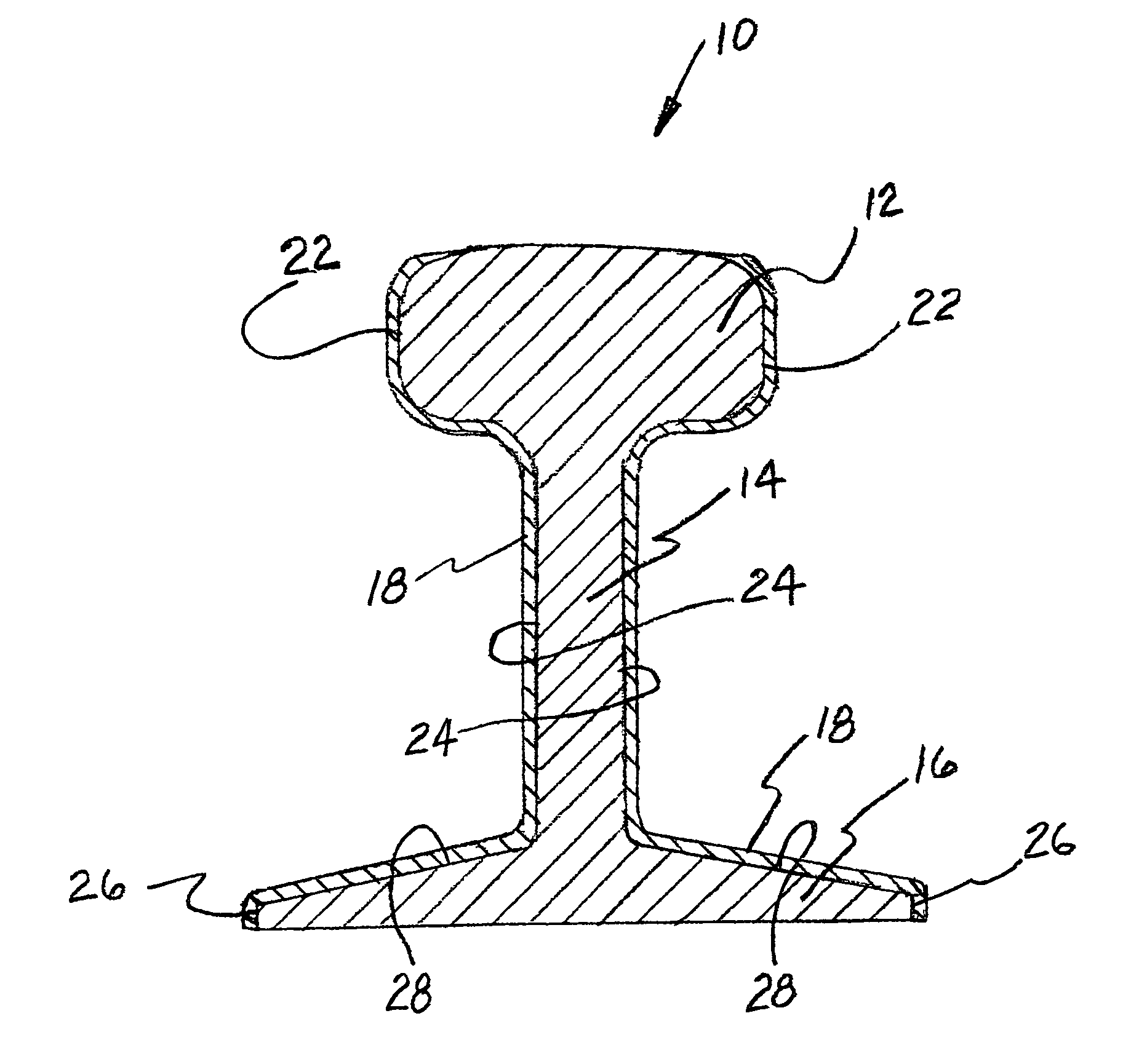
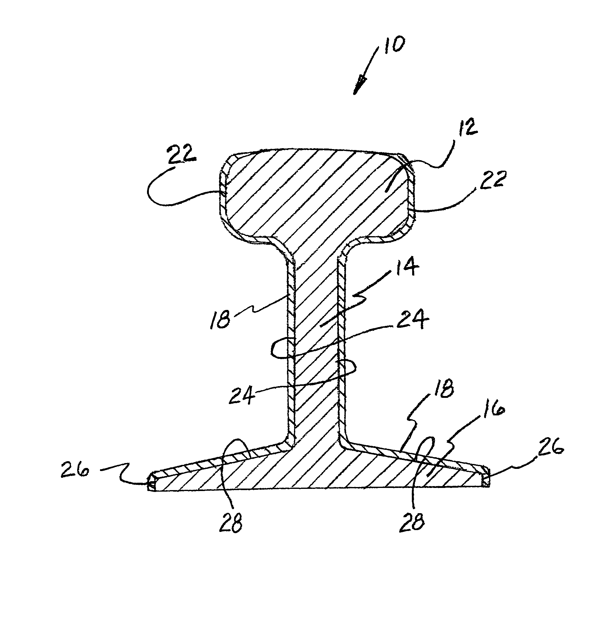
[0026]According to the invention, there is provided a method of reducing the heat absorption of a rail installed as part of a track structure. By reducing such heat absorption there is a decrease in the detrimental expansion of the rail achieved.

[0027]The method includes selecting a ceramic based insulating type paint having a predetermined capability of resisting heat buildup in such rail. The presently preferred ceramic based insulating paint is one presently manufactured and marketed by Superior Products International, Inc. under the Trademark Super Therm®. This particular paint product has four different ceramic materials to achieve its enhanced insulating capability. Each of these four ceramics provide certain preselected desirable characteristics to the insulating paint. These characteristics include heat reflection, dead air space and blocking of infrared rays. Additionally, as shown in a 180 degree bending test, this particular ceramic based insulating paint exhibits excelle...

second embodiment

[0031] the present invention provides a method of forming a heat resistant rail to be installed in a track structure at the rail manufacturing facility. This method includes the steps of selecting a ceramic based insulating type paint, as described above, having a predetermined capability of resisting heat buildup in the rail to be coated with such paint. The ceramic based insulating type paint selected is effective in blocking heat from each of radiation, convection and conduction. In addition, the ceramic based insulating type paint selected should be non toxic.

[0032]The method also requires removing any rolling oil and other contaminants from a surface area of at least certain predetermined portions of such rail prior to coating.

[0033]Thereafter, applying such ceramic based insulating type paint selected to the predetermined portions of such rail and installing such rail pre-coated with such ceramic based insulating type paint selected and applied to such predetermined portions o...


PUM


Abstract

A railroad rail having superior thermal expansion characteristics. Such railroad rail comprising a rail having a predetermined weight and a predetermined length and a ceramic based insulating type paint having a predetermined capability of resisting heat buildup in such rail adhered to predetermined areas of such rail.

Description

CROSS REFERENCE TO RELATED APPLICATIONS[0001]This patent application is both related to and claims priority from U.S. Provisional Patent Application Ser. No. 60 / 729,687 filed Oct. 24, 2005.FIELD OF THE INVENTION[0002]The present invention relates, in general, to railroad rails including the thermal expansion of such railroad rails and, more particularly, this invention relates to a method of significantly reducing the detrimental thermal expansion of the existing railroad rails and further to a method of producing a new railroad rail having an improved resistance to such thermal expansion.BACKGROUND OF THE INVENTION[0003]As is generally well known in the railway industry art, during hot weather, particularly in certain areas of the country, railroad rails will expand and depending upon the degree of such expansion they can buckle. Such buckling can cause a number of difficulties not the least of which is derailment of a train running of such rails. These derailments are not only cos...

Claims


Application Information

Patent Timeline
Patent Type & Authority Patents(United States)
IPC IPC(8): E01B11/00
CPCE01B19/00
Inventor JONES, PAUL
Owner JONES PAUL
Why Eureka
Try Eureka