Document feeder with pivoting delivery table, particularly for digital printers

a feeder and delivery table technology, applied in the field of sheet feeders, can solve the problems of small limits on the size of the stack of sheets, inability to feed difficult or thick sheets, and inability to use large volumes of printing, etc., and achieve the effect of dramatic increase in the production capacity of the printer

Active Publication Date: 2013-07-23
KAIPING JAMES C
View PDF8 Cites 7 Cited by
  • Summary
  • Abstract
  • Description
  • Claims
  • Application Information

AI Technical Summary

Benefits of technology

[0007]The present invention provides a friction feeder assembly that is designed to be positioned near a printer's manual feed tray, and feed sheets, one at a time, to the manual feed tray feed roller, increasing dramatically the production capability of the printer when printing envelopes or other difficult sheets. Most commonly, the printer will be a digital printer, and the sheets will be envelopes or cards, but the invention is not limited thereto. Preferably and advantageously, no modification of the printer's manual feed tray or of the printer's sensors and electronics is required. The feeder assembly of the present invention may also be used with devices other than printers which incorporate a top-feed mechanism that draws sheets from the top of a stack.
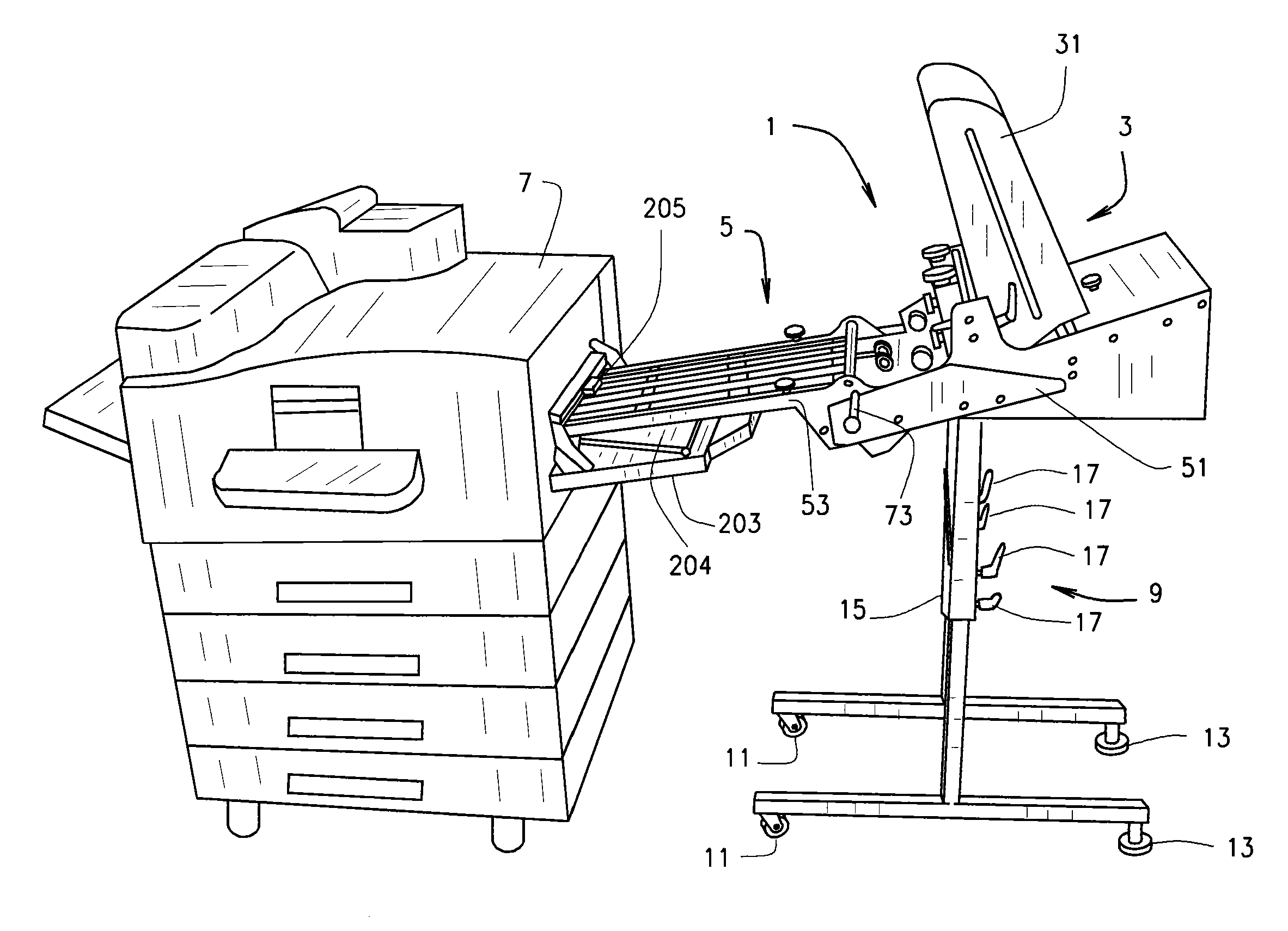
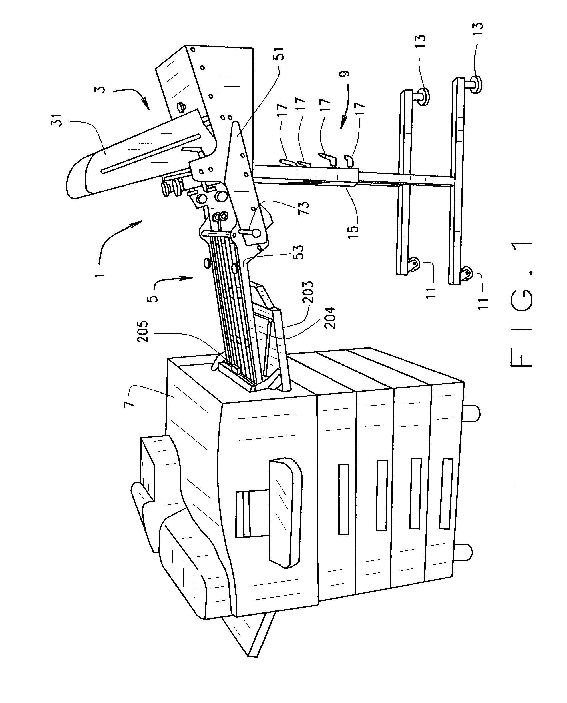
[0009]The feeder assembly of the present invention obviates the need to remove the manual feed tray from the printer by incorporating a delivery table that is attached to the feeder, and extends laterally away from the feeder in the direction of the printer. One end of this table is pivotally attached to the feeder, leaving the end closest to the printer vertically movable, so that it can be raised up while the feeder is moved into position adjacent the printer to clear the upwardly tilting manual feed tray described above and then tilted back down onto the manual feed tray to allow the end of the table to be positioned under the feed roller of the printer. When the feeder is placed in the proper position, the exit end of the delivery table is positioned just below the feed roller of the digital printer. When the printer is started, the manual feed tray is raised slightly by internal components of the printer. When this tray which is underneath the delivery table of the feeder rises, it lifts the pivoting delivery table up until it, or a sheet at its free end, activates the printer's top-of-stack sensor. By allowing the printer to lift the delivery table to the proper height, the delivery table is positioned exactly as needed to deliver the documents to the printer without interference.
[0011]Since varying digital printers incorporate various manual feed tray designs and specifications, including height, the pivoting delivery table of the feeder of the present invention offers the ability to use it with a wide variety of printers. As described earlier, the manual feed tray of the digital printer typically rises a bit to push documents up to the feed roller. Since the rising force of these manual feed trays will vary, the pivoting delivery table may include an adjustable counter-balance or spring-loaded mechanism that reduces the effective weight of the delivery table and aids the feed tray in lifting the end of the delivery table to the proper height of the feed roller. The balance mechanism used in the preferred embodiment of the present invention is an adjustable spring, but it can also be an adjustable weight or shock absorbing device, for example. Preferably, the adjustable balance mechanism is capable of reducing the effective weight of the delivery table on the feed tray by at least 10%, desirably by at least 25%, and preferably by at least 50%.
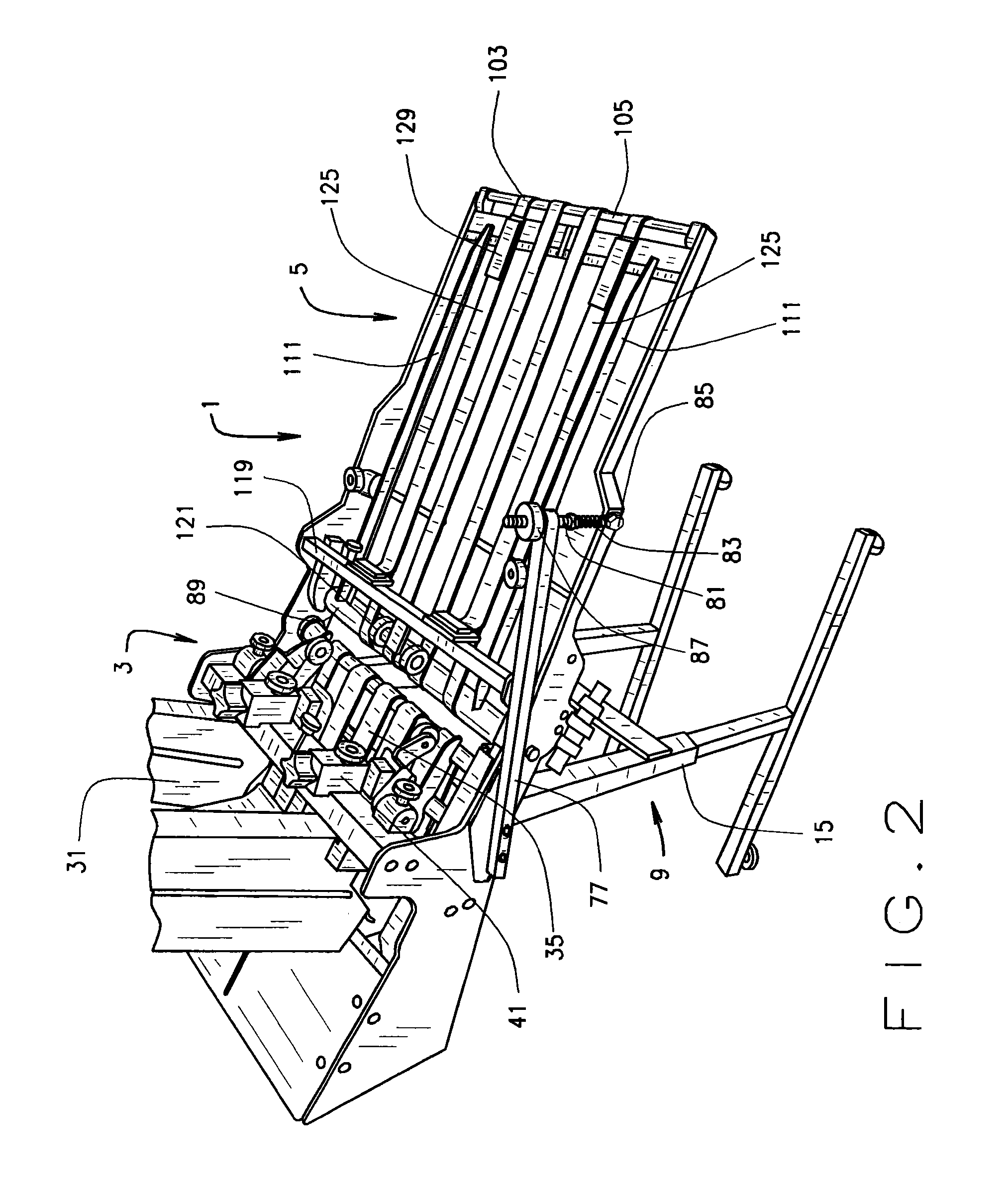
[0012]The delivery table of the preferred embodiment includes a drive roller at its rearward, or upstream, end. The drive roller is conveniently driven by a timing belt trained around a pulley on a drive roller of the feeder. This arrangement ensures that movement of sheets across the delivery table is synchronized with ejection of sheets from the sheet feeder. The delivery table drive roller pulley is preferably somewhat smaller than the drive roller of the feeder, so that the delivery table belts travel faster than the feeder belts, thereby separating the sheets on the delivery table from each other. Delivery table feed belts are trained around the delivery table drive roller and around an exit shaft at the downstream, exit, end of the delivery table. These delivery table feed belts are used to advance the sheets away from the feeder's hopper area and toward the printer's manual feed tray feed roller. The exit shaft has a one-way bearing of sufficient diameter to urge the sheet into the digital printer top-feed pulling roller; the one-way bearing spinning freely when the top-feed roller accelerates the sheet into the printer. A sensor, illustratively a photo-eye, at the exit end of the delivery table detects the leading edge of the foremost advancing sheet and signals the feeder to stop advancing the sheet once it has reached the proper position under the printer's feed roller. When the printer's feed roller advances the foremost sheet into the printer, the sensor detects the absence of a sheet and calls for the feeder assembly to deliver another sheet to the exit end of the delivery table.
[0013]With the freely pivoting delivery table of the present invention, the user of the digital printer can slide the feeder into position next to the digital printer without removing any components of the digital printer or circumventing any of the electronic sensors or switches on the printer. An additional advantage is that the operator can also easily move the feeder away from the printer and use the manual feed tray normally, since it does not need to be re-attached.

Problems solved by technology

Although this method works very well on standard paper, it is not capable of feeding difficult or thick sheets, such as envelopes, postcards, folded pieces, and other thick materials.
Although these manual feed trays work reasonably well, they have very small limits on the size of the stack of sheets, and therefore cannot be used for large volumes of printing without constant re-loading of media.
This means that the operator cannot load documents into the feed tray until the prior stack is depleted.

Method used


Image

  • Document feeder with pivoting delivery table, particularly for digital printers
  • Document feeder with pivoting delivery table, particularly for digital printers
  • Document feeder with pivoting delivery table, particularly for digital printers

Examples


Embodiment Construction

[0022]Referring to the drawings, reference numeral 1 indicates a sheet feeder assembly including a sheet feeder 3 having pivotably attached thereto a delivery table 5. The sheet feeder assembly 1, in this mode of carrying out the invention, interacts with a digital copying machine / printer 7 as described below.

[0023]The sheet feeder assembly 1 is mounted on a stand 9 having wheels 11 and adjustable feet 13. The stand 9 has telescoping legs 15 with locks 17 for setting the height of the sheet feeder assembly 1. If the floor on which the stand 9 rests is always expected to be level with the section of floor on which the digital printer 7 rests, the locks 17 may be pins which lock into holes in the legs 15. Otherwise, the locks 17 may be frictional locks of well-known design, to allow slight variance in the heights of the legs 15.

[0024]Sheet feeders 3 useable with the present invention are well known in the art. Although the structure of the sheet feeder 3 is not critical to the inventi...


PUM


Abstract

A sheet feeder assembly (1) includes a bottom-feed sheet feeder (3) and a delivery table (5) positioned to receive sheets from the sheet feeder and deliver the sheets one at a time to a top-feed mechanism (205) designed to feed the top sheet of a stack of sheets in a manual feed tray of a printer (7) or the like. The top-feed mechanism includes a lifting support (204) for a stack of sheets. An exit end of the delivery table rests on and moves with the lifting support and delivers sheets one at a time to the top-feed mechanism. A balance mechanism (75) reduces the effective weight of the delivery table.

Description

CROSS REFERENCE TO RELATED APPLICATIONS[0001]This application is a national stage application under 35 U.S.C. §371 of International application No. PCT / US2010 / 048425, filed Sep. 10, 2010. which. claims priority to U.S. provisional application 61 / 241,209, filed Sep. 10, 2009, and U.S. provisional application 61 / 372,745, filed Aug. 11, 2010, both all of which are hereby incorporated herein by reference.TECHNICAL FIELD[0002]This invention relates generally to sheet feeders for use with devices having an externally accessible feed mechanism that pulls a sheet from a stack of sheets. It has particular but not exclusive usefulness in feeding sheets to a bypass tray of a high speed digital printer (such as a laser printer, an LED printer, or an ink jet printer) which prints an image based on a digital file downloaded to the printer.BACKGROUND ART[0003]There are thousands of digital printers sold each year by many different manufacturers. Digital printing technology has been widely used for...

Claims


Application Information

Patent Timeline
Patent Type & Authority Patents(United States)
IPC IPC(8): B65H3/44B65H5/26
CPCB65H3/042B65H7/02B65H11/002B65H3/44G03G15/60B65H2701/1916B65H2801/06B65H2405/312G03G2215/0021B65H2407/21B65H2402/42
Inventor KAIPING, JAMES C.
Owner KAIPING JAMES C
Why Eureka
Try Eureka