
Self-adjusting trim assembly at flexible ceiling and stationary wall junction

a technology for ceiling and stationary walls and trim assemblies, which is applied in the directions of walls, parkings, special buildings, etc., can solve problems such as unseemly gaps

Active Publication Date: 2013-07-30
DGT
View PDF36 Cites 64 Cited by
  • Summary
  • Abstract
  • Description
  • Claims
  • Application Information

AI Technical Summary

Benefits of technology

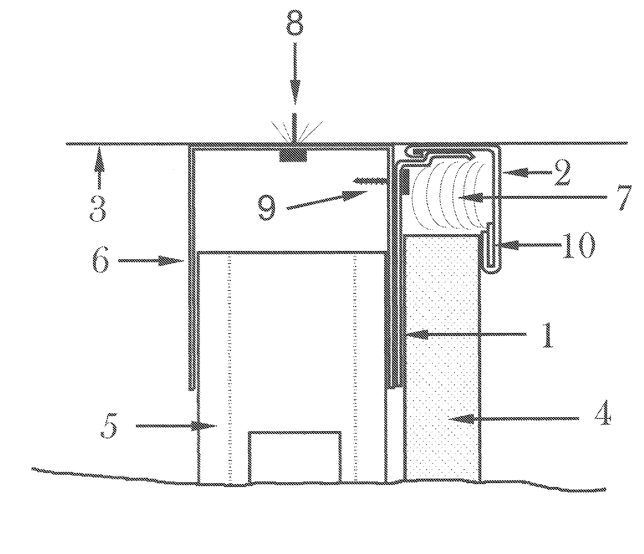
The present invention is a self-adjusting trim system that can be used in any building where the ceilings are expected to flex due to the construction materials and support structures, while the wall finishes abutting the ceilings are expected to remain stationary. The system allows for the expected movement of the ceiling while keeping the wall finishes aesthetically pleasing. The key effect of this system is that it provides a solution for the issue of unappealing gaps between the inverted ceilings and stationary walls. Additionally, the system is economical and easy to install.

Problems solved by technology

To allow for the expected movement of the ceiling an unsightly gap must exist between the top of the stationary wall finishes and the flexing ceiling.

Method used


Image

  • Self-adjusting trim assembly at flexible ceiling and stationary wall junction
  • Self-adjusting trim assembly at flexible ceiling and stationary wall junction
  • Self-adjusting trim assembly at flexible ceiling and stationary wall junction

Examples


Embodiment Construction

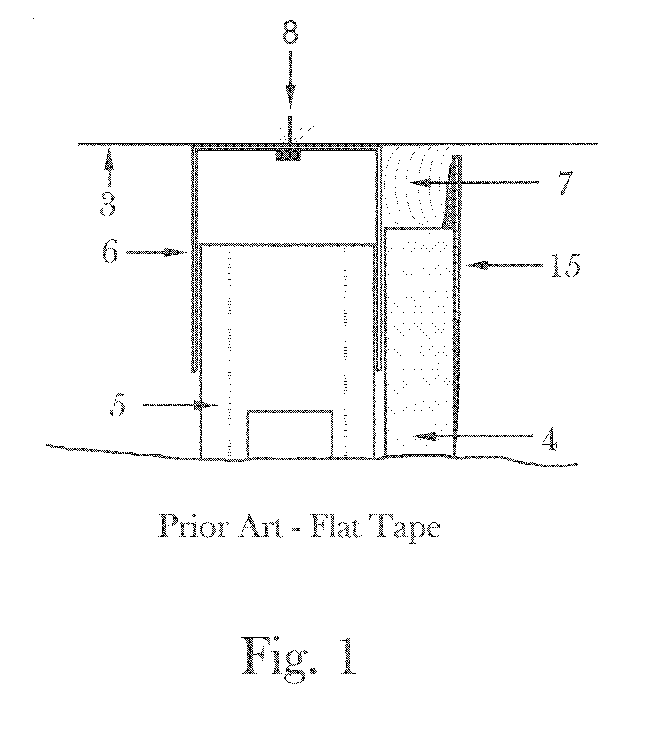
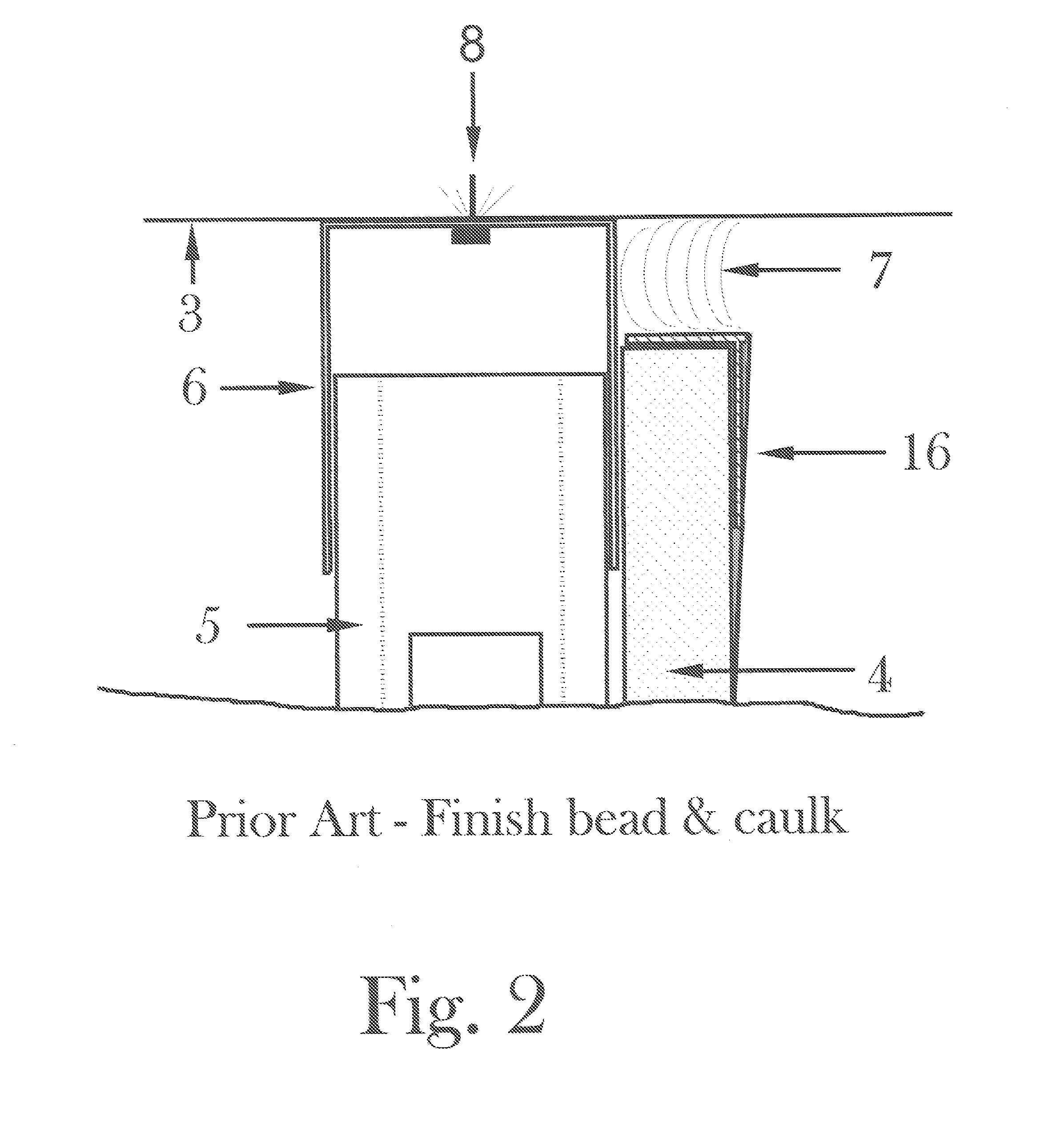
[0044]FIG. 1 shows the common, aesthetic treatment of the necessary gap between the top of the stationary wall finish and the ceiling that is expected to flex due to expansion, contraction and other anticipated movement of the support walls at each end of the ceilings. Note that the paper tape and finishing compound 15 is applied to the top edge of the wall finish 4 with a gap between the tape and compound 15 and the ceiling 3 above. Also shown are the framing components of this typical construction designed to allow for ceiling flex (vertical framing component 5 in a deflection or slip track 6), and caulk 7 in the gap between the top of the wall finish 4 and the ceiling 3. The problem with this construction results during the anticipated upward and downward travel of the ceiling 3, which crushes the top of the flat tape and compound 15 and then exaggerates the gap at the top of the tape when the ceiling 3 flexes in an upward direction. This treatment of the wall finish and ceiling ...


PUM


Abstract

A self-adjusting trim assembly used at the junction of a wall and ceiling where the wall finishes are to remain stationary while the ceiling is expected to flex due to loads on ceiling structure and normal variations in the height of the supporting structures due to temperature, moisture, creep or other factors effecting the height of the support structures. This trim assembly has two interlocking components comprised of a retainer clip having a vertical back portion (1a), a horizontal projecting tongue (1b) and the interlocking hook portion (1c) and also of a trim strip having a horizontal top portion (2a), a vertical face portion (2b) and an interlocking hook portion (2c) with the vertical face portion of the trim strip designed to cover the gap between stationary wall finishes and a flexing ceiling while trim strip remains flush with the ceiling structure, thus leaving no unsightly gap.

Description

BACKGROUND OF THE INVENTIONS[0001]1. Technical Field[0002]The present inventions relate to the components and the procedure for installing a trim assembly at a wall and ceiling junction, and, more particularly, relates to a self-adjusting trim assembly designed to hide unsightly gaps at the junction between the top of a stationary wall finish and a ceiling expected to move.[0003]2. Description of the Related Art[0004]As construction techniques improved in recent years, free span concrete ceilings (poured or pre-cast spans devoid of columns and beams for intermediate support) have come into common usage. These free span structures are usually supported by interior walls or beams at the core of the building and by walls or beams at the exterior of the building.[0005]Exterior support structures are frequently subject to temperature variances and forces not present on and around the interior (core) support structures. The dynamics involved with the exterior support structures cause them...

Claims


Application Information

Patent Timeline
IPC IPC(8): E04B2/00
CPCE04F19/061E04F19/0463E04F19/0436E04F2019/0422E04F2019/0413
Inventor JOHNSON, SR., THOMAS W
Owner DGT
Learn More