Device and method for supplying gas while dividing to chamber from gas supplying facility equipped with flow controller

a technology of flow controller and gas supply device, which is applied in the direction of valve operating means/releasing devices, process and machine control, instruments, etc., can solve the problems of limiting the flow control range capable of being used, reducing the accuracy of flow control in reality, and inability to perform flow control, etc., to achieve accurate and rapid operation, reduce facility costs, and facilitate the effect of operation

Inactive Publication Date: 2013-07-30
FUJIKIN INC +1
View PDF21 Cites 15 Cited by
  • Summary
  • Abstract
  • Description
  • Claims
  • Application Information

AI Technical Summary

Benefits of technology

[0037]The present invention provides a device for supplying gas while dividing to a chamber from a gas supply facility equipped with a flow controller which is so constituted that, with a device for supplying a specified quantity Q of processing gas while dividing at a specified flow rate ratio Q2 / Q1 from a gas supply facility 1 equipped with a flow controller QCS into a chamber C through a plurality of branch supply lines GL1 and GL2 and shower plates 3 and 4 fixed to the ends thereof, a division quantity controller 2 comprising an open / close valves OV1 and OV2 installed on an afore-mentioned plurality of branch supply lines GL1 and GL2 respectively, a bypass line BL1 branched from a branch supply line GL1 on the downstream side of the open / close valve OV1, a bypass line BL2 branched from a branch supply line GL2 on the downstream side of the open / close valve OV2, a pressure type division quantity controller FV connected to the bypass line BL1 and the bypass line BL2, a pressure sensor PS1 to measure pressure inside the branch supply line GL1, and a pressure sensor PS2 to measure pressure inside the branch supply line GL2 is installed between the afore-mentioned gas supply facility 1 and a chamber C so that a specified quantity Q of gas is supplied while dividing into the chamber at a specified flow rate ratio Q1 / Q2 through shower plates 3 and 4 fixed to the ends of branch supply lines GL1 and GL2.
[0038]As a result, pressure control on a number of flow rate ratios Q2 / Q1 becomes possible accurately and quickly with the pressure type division, quantity controller, thus achieving an excellent effect of making facility costs lowered.
[0039]The present invention provides a method for supplying gas while dividing to a chamber from a gas supply facility equipped with a flow controller characterized by that, with a method for supplying a specified quantity Q of processing gas while dividing at a specified flow rate ratio Q1 / Q2 from a gas supply facility 1 equipped with a flow controller QCS into a chamber through a plurality of branch supply lines GL1 and GL2 and shower plates 3 and 4 fixed to the ends thereof, a division quantity controller 2 comprising an open / close valves OV1 and OV2 installed on an afore-mentioned plurality of branch supply lines GL1 and GL2 respectively, a bypass line BL1 branched from a branch supply line GL1 on the downstream side of the open / close valve OV1, bypass line BL2 branched from a branch supply line GL2, a pressure type division quantity controller FV connected to the bypass line BL1 and the bypass line BL2, a pressure sensor PS1 to measure pressure inside the branch supply line GL1, and a pressure sensor PS2 to measure pressure inside the branch supply line GL2 is installed between the afore-mentioned gas supply facility 1 and a chamber C, and also that a total quantity Q=Q1+Q2 of gas while dividing is supplied into the afore-mentioned chamber C at desired flow rates Q1 and Q2 by regulating pressure of the branch supply line GL1 and the branch supply line GL2 by opening the open / close valve of a branch supply line having a larger flow, to adjust the degree of opening of the afore-mentioned pressure type division quantity controller FV, thus adjusting a flow rate of gas running from a branch supply line having a larger flow rate of supply to a branch supply line having a smaller flow rate of supply, to regulate pressure of the branch supply line GL1 and the branch supply line GL2.
[0040]As a result, pressure control on a number of flow rate ratios Q2 / Q1 can be performed accurately and quickly with one set of pressure type division quantity controller, thus achieving excellent effects of making facility costs lowered and pressure control easier.

Problems solved by technology

The drawback is that the flow control cannot be performed because the critical expansion pressure condition is not satisfied, for example, when gas pressure P2 on the downstream side of the orifice rises more than gas pressure P1 on the upstream side of the orifice.
Another drawback is that flow control accuracy is lowered in reality when P1 / P2 reaches closer the limit value of the afore-mentioned critical pressure condition with the rise of pressure P2 on the downstream side of the orifice.
Thus limiting the flow control range capable of being used when pressure P2 on the downstream side rises.
However, to supply gas using gas supply lines GL1 and GL2 both of which are equipped with a pressure type flow controller FCS1 and FCS2 independently into a chamber invites a rise in installation costs as well as upsizing of a semiconductor manufacturing facility, and is also found to be time-consuming for its maintenance.
For these reasons, the method is undesirable.
This, however, finds it difficult to control the flow rates accurately and quickly.
However, on the other hand, the method made the control complicated because it employed two pressure type division quantity controllers FV1 and FV2 beside a pressure type flow controller FCS for regulating pressure on both sides, thus inviting another problem of facility costs becoming higher.Patent Literature 1: TOKU-KAI-HEI No. 8-338546 Public BulletinPatent Literature 2: TOKU-KAI-HEI No. 11-63265 Public Bulletin

Method used


Image

  • Device and method for supplying gas while dividing to chamber from gas supplying facility equipped with flow controller
  • Device and method for supplying gas while dividing to chamber from gas supplying facility equipped with flow controller
  • Device and method for supplying gas while dividing to chamber from gas supplying facility equipped with flow controller

Examples


Embodiment Construction

[0049]The embodiment in accordance with the present invention is described hereunder with reference to the drawings.

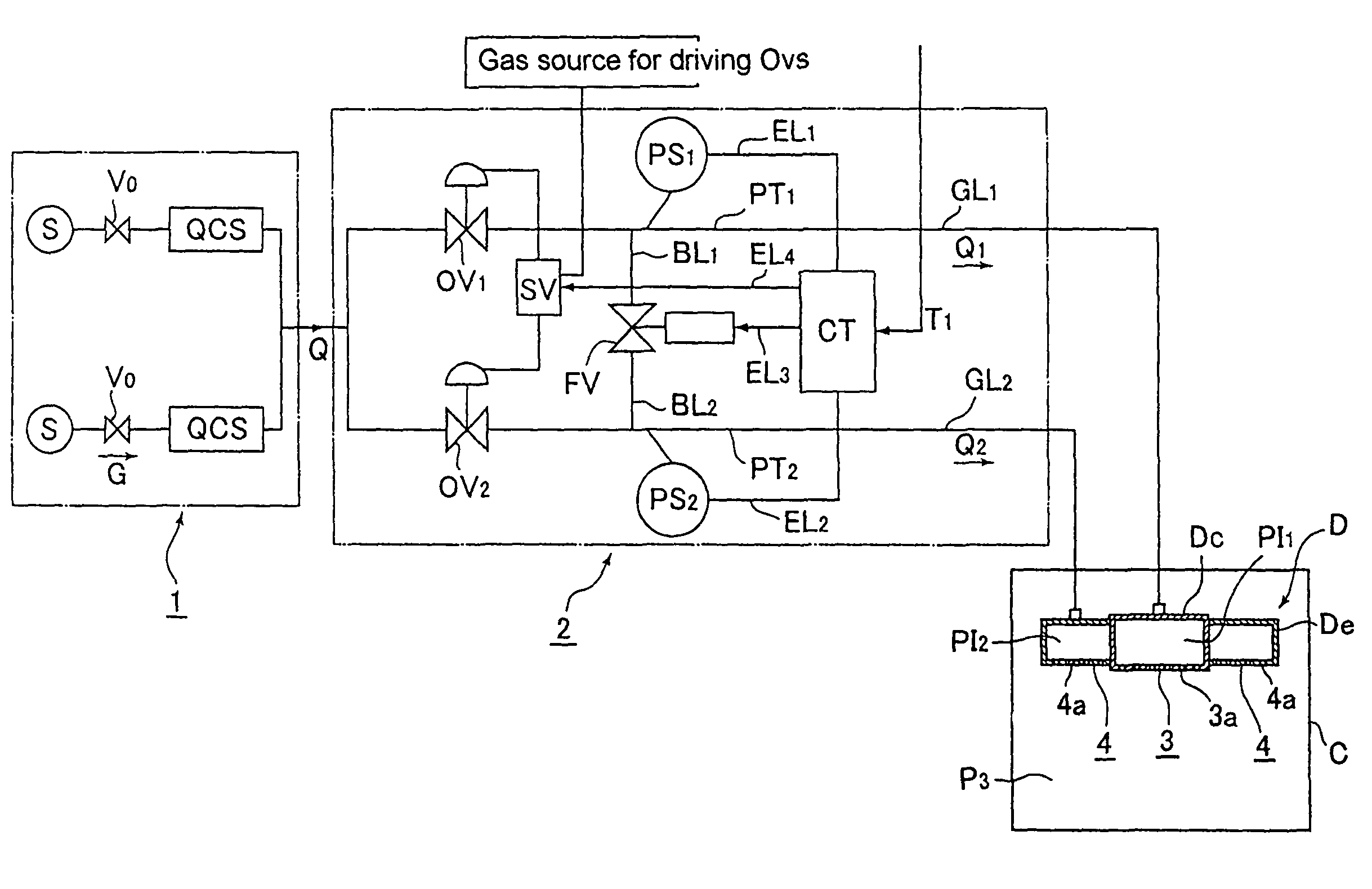
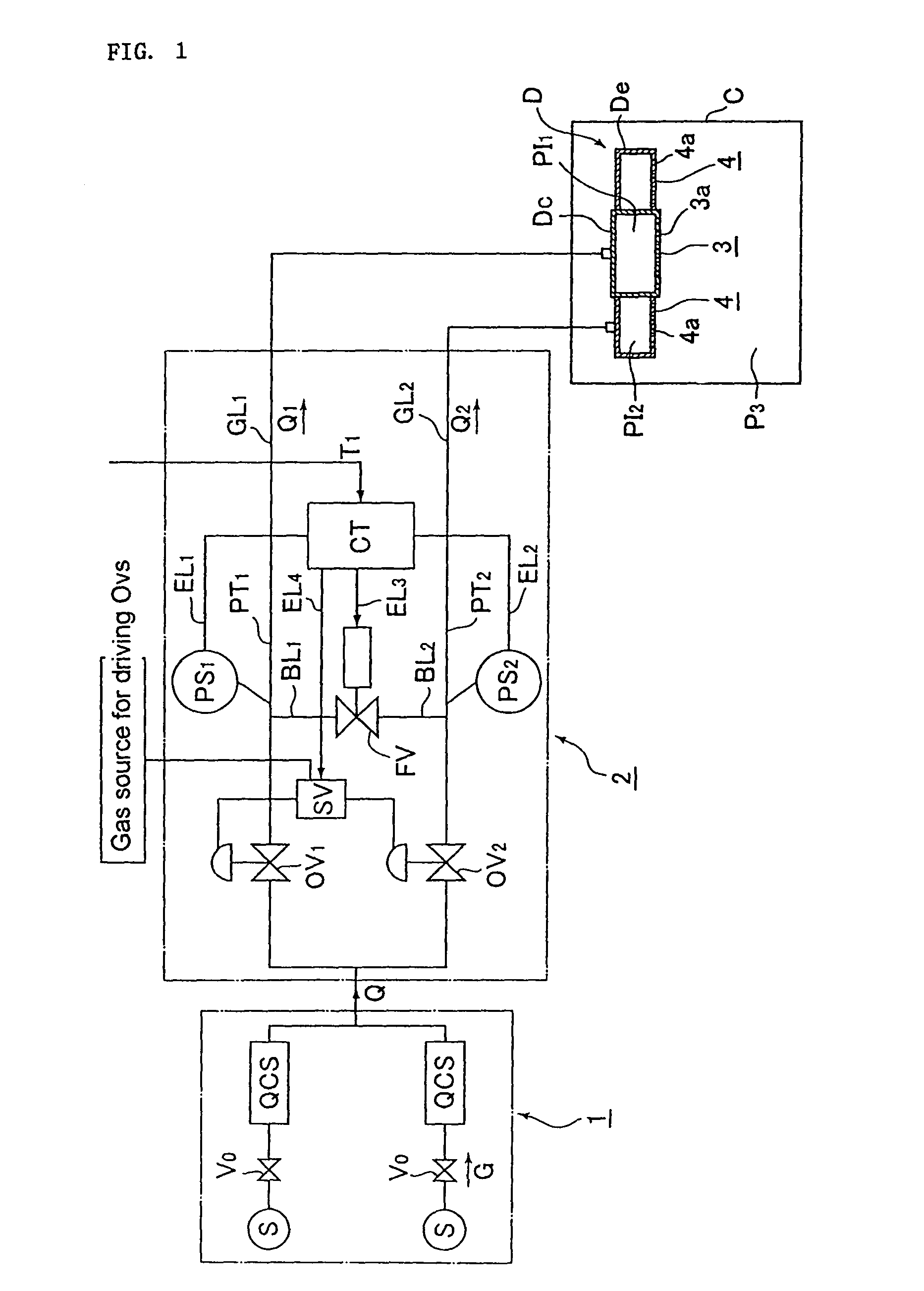
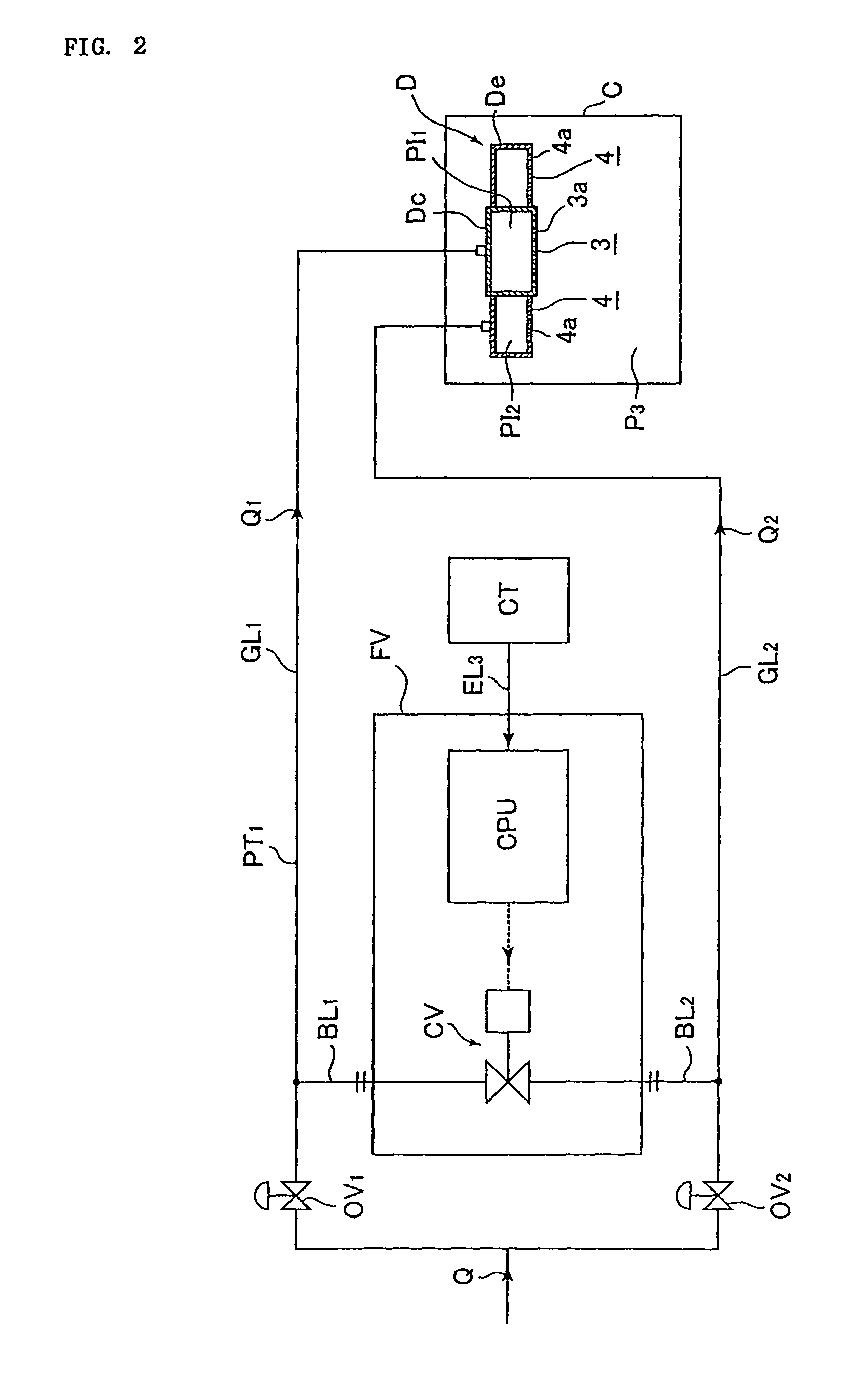
[0050]FIG. 1 is an overall schematic diagram to explain a device and a method for supplying gas while dividing to a chamber from a gas supply facility equipped with a flow controller QCS according to the present invention. In FIG. 1, a gas supply facility 1 comprises a supply source S of processing gas G, a gas main valve V0, a flow controller QCS and the like. A division quantity controller 2 comprises a pressure type division quantity controller FV, a communication control circuit CT and the like.

[0051]Further, in FIG. 1, C designates a chamber, D a gas discharger, Dc a gas discharger for the center part, De a gas discharger for the edge part, GL1 a branch supply line for the center part, GL2 a branch supply line for the edge part, Q a total quantity of gas, Q1·Q2 flow rates while dividing, PT1·PT2 pressure in branch supply lines GL1 and GL2, P3 pressure inside a cha...


PUM


Abstract

The invention supplies a quantity Q of gas while dividing at flow rate ratio Q1 / Q2 from a gas supply facility equipped with a flow controller. A total quantity Q=Q1+Q2 of gas is supplied into a chamber at flow rate Q1 and Q2 through shower plates fixed to ends of branch supply lines by providing open / close valves with a plurality of branch supply lines GL1 and GL2, respectively, to supply the specified quantity of gas from the gas supply facility, and by utilizing bypass line BL1 on the downstream side of the open / close valve OV1 and branched from GL1 ,bypass line BL2 on the downstream side of the open / close valve OV2 and branched from GL2 ,pressure type division quantity controller connected to the bypass line BL1 and the bypass line BL2 ,a sensor measuring pressure inside branch supply line GL1 ,and another sensor measuring pressure inside branch supply line GL2.

Description

[0001]This is a National Phase Application in the United States of International Patent Application No. PCT / JP2004 / 008117 filed Jun. 10. 2004, which claims priority on Japanese Patent Application No. 2003-177134, filed Jun. 20, 2003. The entire disclosures of the above patent applications are hereby incorporated by reference.FIELD OF THE INVENTION[0002]The present invention is to be used for semiconductor manufacturing facilities, and is concerned with improvements in supplying gas while automatically dividing to a chamber from a gas supplying facility equipped with a flow controller.BACKGROUND OF THE INVENTION[0003]A device called a pressure type flow controller has been widely used for flow control of gas to be supplied to a chamber of a semiconductor manufacturing facility.[0004]FIG. 5 illustrates an example in the event that processing gas G is supplied into a chamber to form a silicon oxide film using a pressure type flow controller FCS. A specified quantity Q of processing gas...

Claims


Application Information

Patent Timeline
Patent Type & Authority Patents(United States)
IPC IPC(8): G05D11/13G05D7/06F17D1/04H01L21/02H01L21/31
CPCG05D7/0664G05D7/00G05D7/0658G05D11/132G05D7/0623G05D7/0652Y10T137/2521Y10T137/0396Y10T137/0379Y10T137/263Y10T137/2529Y10T137/2663Y10T137/8175Y10T137/2562Y10T137/7761G05D7/06
Inventor SUGIYAMA, KAZUHIKOIKEDA, NOBUKAZUNISHINO, KOUJIDOHI, RYOUSUKEUENOYAMA, TOYOMI
Owner FUJIKIN INC
Why Eureka
Try Eureka