Turbine ring assembly for gas turbine

a technology for turbine rings and gas turbines, applied in the direction of air transportation, motors, leakage prevention, etc., can solve problems such as complexness, and achieve the effect of reducing gas leakag

Active Publication Date: 2013-07-30
SAFRAN CERAMICS SA
View PDF28 Cites 29 Cited by
  • Summary
  • Abstract
  • Description
  • Claims
  • Application Information

AI Technical Summary

Benefits of technology

[0008]An object of the invention is to propose a simplified assembly for a turbine ring made of CMC material that also minimizes gas leakage between the outside of the ring and the flow section through the ring for the stream of hot gas.
[0014]Thus, with a complete CMC ring as a single part placed between two annular supports that may each of them also constitute a single part, i.e. without segments, the structure of the turbine ring assembly is simplified and any leakage between ring sectors is avoided. In addition, using a CMC material makes it possible to reduce cooling requirements, thereby reducing requirements in terms of cooling air flow.

Problems solved by technology

Nevertheless, it is necessary to design an assembly for the ring sectors that is rather complex in order to accommodate the difference between the coefficients of expansion of a CMC material and of the material of a metal casing in which the ring sectors are assembled, and while minimizing leaks against adjacent sectors.

Method used


Image

  • Turbine ring assembly for gas turbine
  • Turbine ring assembly for gas turbine
  • Turbine ring assembly for gas turbine

Examples


first embodiment

[0035]a turbine ring assembly in accordance with the invention is described with reference to FIGS. 1 to 8.

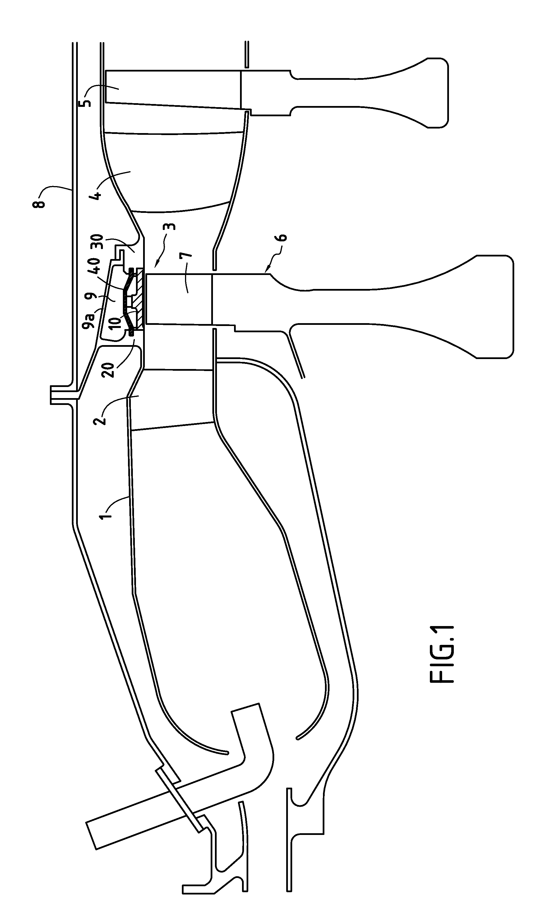
[0036]FIG. 1 shows, in highly diagrammatic manner, and from upstream to downstream in the flow direction of gas through a gas turbine: a combustion chamber 1; a turbine nozzle 2 placed at the outlet from the combustion chamber; a high pressure (HP) turbine 3; a flow straightener 4; and a first stage of a low pressure (LP) turbine 5.

[0037]The HP turbine 3 comprises a turbine wheel 6 that is movable in rotation and that carries blades 7, and a turbine ring assembly.

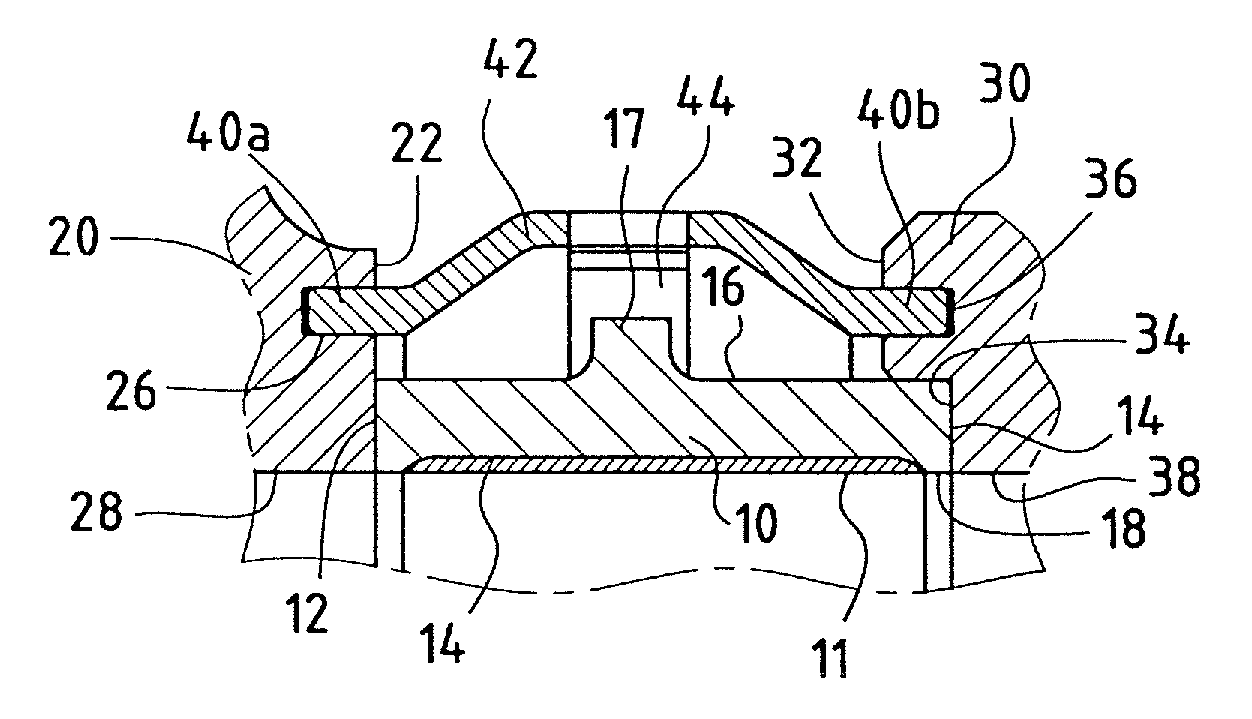
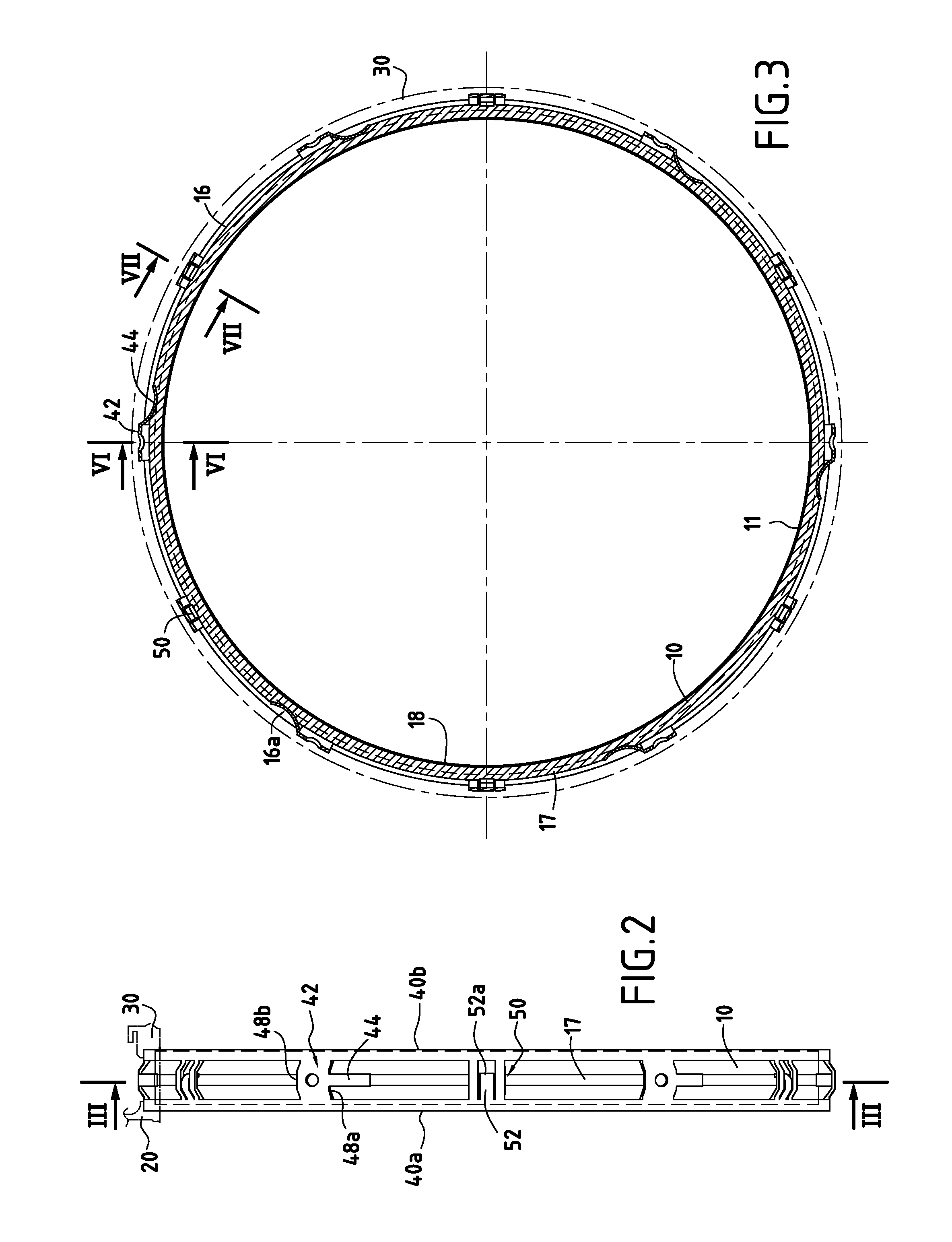
[0038]The turbine ring assembly comprises a turbine ring 10 that is complete, i.e. it is not interrupted and forms a single part, being made of CMC material. The CMC ring 10 is supported by a metal support structure comprising a first annular support or upstream annular support 20, and a second annular support or downstream annular support 30, between which the ring 10 is placed and held, together with a metal hoop 40 ...

second embodiment

[0055]the turbine ring assembly in accordance with the invention is described below with reference to FIGS. 9 to 12.

[0056]FIG. 9 is a fragmentary diagrammatic axial half-section view of a gas turbine that differs from FIG. 1 essentially in the shape of the turbine ring 110 and the way it is mounted between a first annular metal support or upstream metal support 120 and a second annular metal support or downstream metal support 130 within the ring assembly of the HP turbine 3, the other elements of the gas turbine being similar to those of FIG. 1 and being given the same references.

[0057]The turbine ring 110 is a complete ring made as a single piece of CMC. The annular metal supports may likewise be in the form of rings that are complete and not segmented.

[0058]As shown in particular in FIG. 10, the inner lateral faces of the annular supports 120 and 130 present frustoconical surface portions 122 and 134. A lateral face of the ring 110 presents a surface 112 of frustoconical shape co...


PUM

PropertyMeasurementUnit
forceaaaaaaaaaa
corrosionaaaaaaaaaa
mechanical propertiesaaaaaaaaaa

Abstract

A turbine ring assembly for a gas turbine, the assembly having a complete ring forming a single piece of ceramic matrix composite material (CMC), a metal structure for supporting the CMC ring having metal annular supports between which the CMC ring is placed while allowing differential expansion at least in a radial direction between the CMC ring and the annular supports, an arrangement for centering the CMC ring, and at least one element for preventing turning of the CMC ring about its axis.

Description

BACKGROUND OF THE INVENTION[0001]The invention relates to turbine rings for gas turbines, whether industrial gas turbines or gas turbines forming aeroengines.[0002]In a gas turbine, a turbine ring defines a flow section at a rotary wheel of the turbine for a stream of hot gas passing therethrough. In order to ensure the best possible efficiency, it is important to avoid gas passing directly between the tips of the blades of the turbine wheel and the inside surface of the ring. Thus, in the usual way, a turbine ring is provided on its inside face with a layer of abradable material with which the turbine tips can come into contact without significant damage under the effect of dimensional variations of thermal origin or as the result of the centrifugal force that is applied to the blades.[0003]Turbine rings are usually made as a plurality of adjacent sectors of metal material.[0004]For example, document U.S. Pat. No. 6,758,653 proposes replacing the metal material of the turbine ring ...

Claims


Application Information

Patent Timeline
Patent Type & Authority Patents(United States)
IPC IPC(8): F01D9/04
CPCF01D9/04F01D11/08Y02T50/67Y02T50/672F05D2240/11F05D2300/21F05D2300/603Y02T50/60
Inventor HABAROU, GEORGESMATEO, JULIENBOUILLON, ERIC
Owner SAFRAN CERAMICS SA
Why Eureka
Try Eureka