

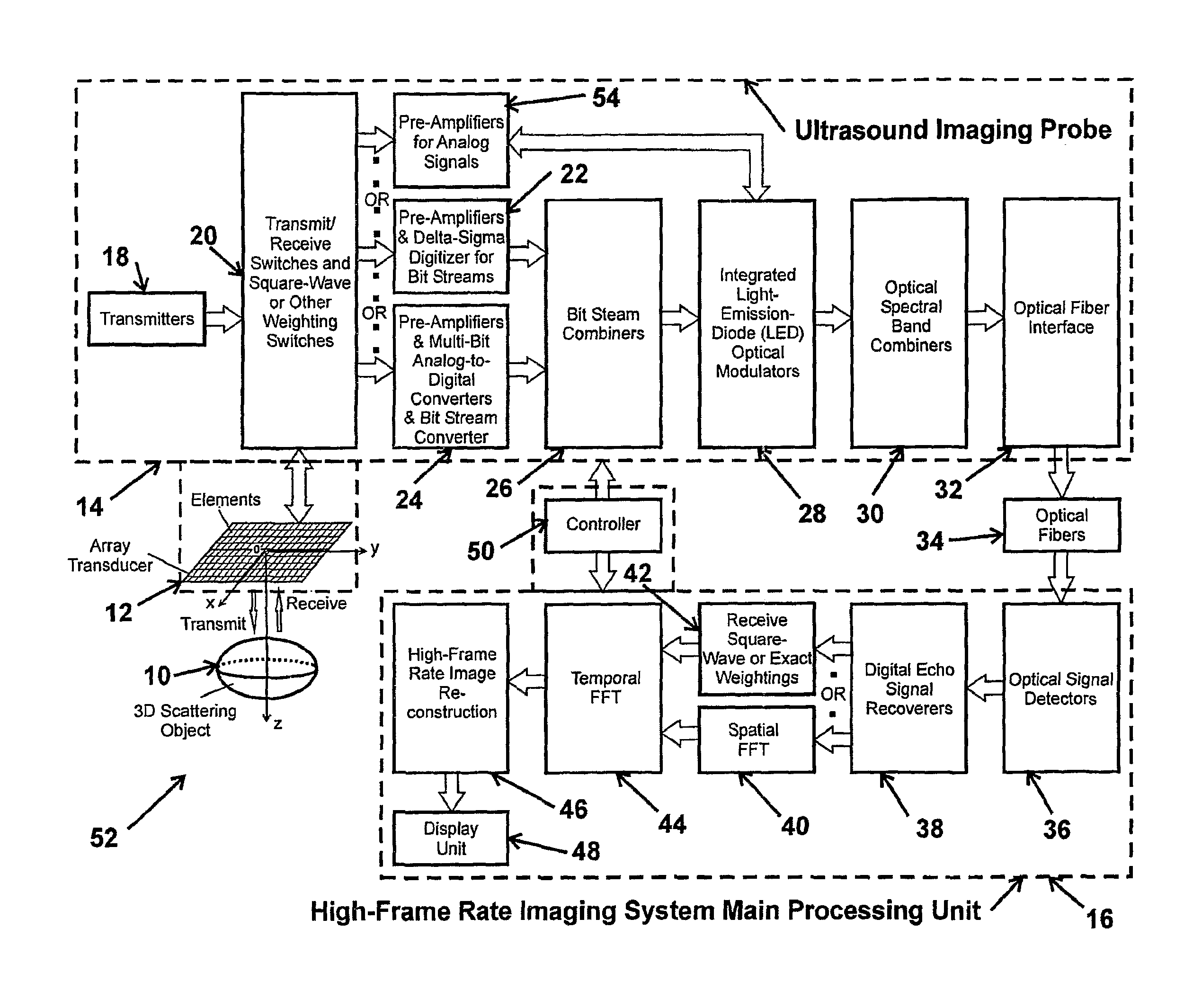
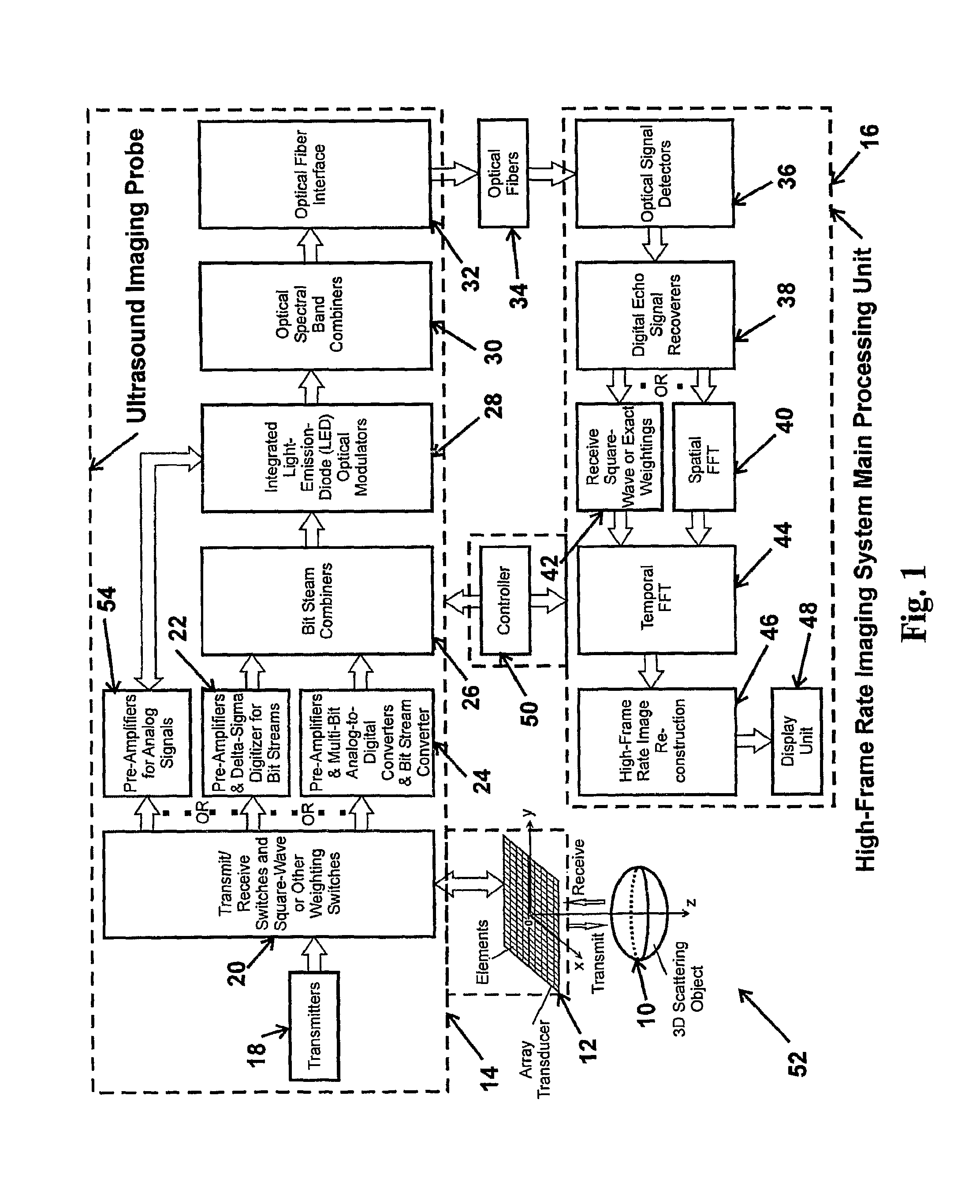
High frame rate imaging system
a high frame rate, imaging system technology, applied in ultrasonic/sonic/infrasonic diagnostics, instruments, applications, etc., can solve the problems of large depth of field, large amount of power, complicated image reconstruction process, etc., and achieve high frame rate, high resolution, and high frame rate
- Summary
- Abstract
- Description
- Claims
- Application Information
AI Technical Summary
Benefits of technology
Problems solved by technology
Method used
Image

Examples
Embodiment Construction
)
[0037]I. High-Frame Rate Imaging System and Square-Wave Aperture Weightings in Transmissions
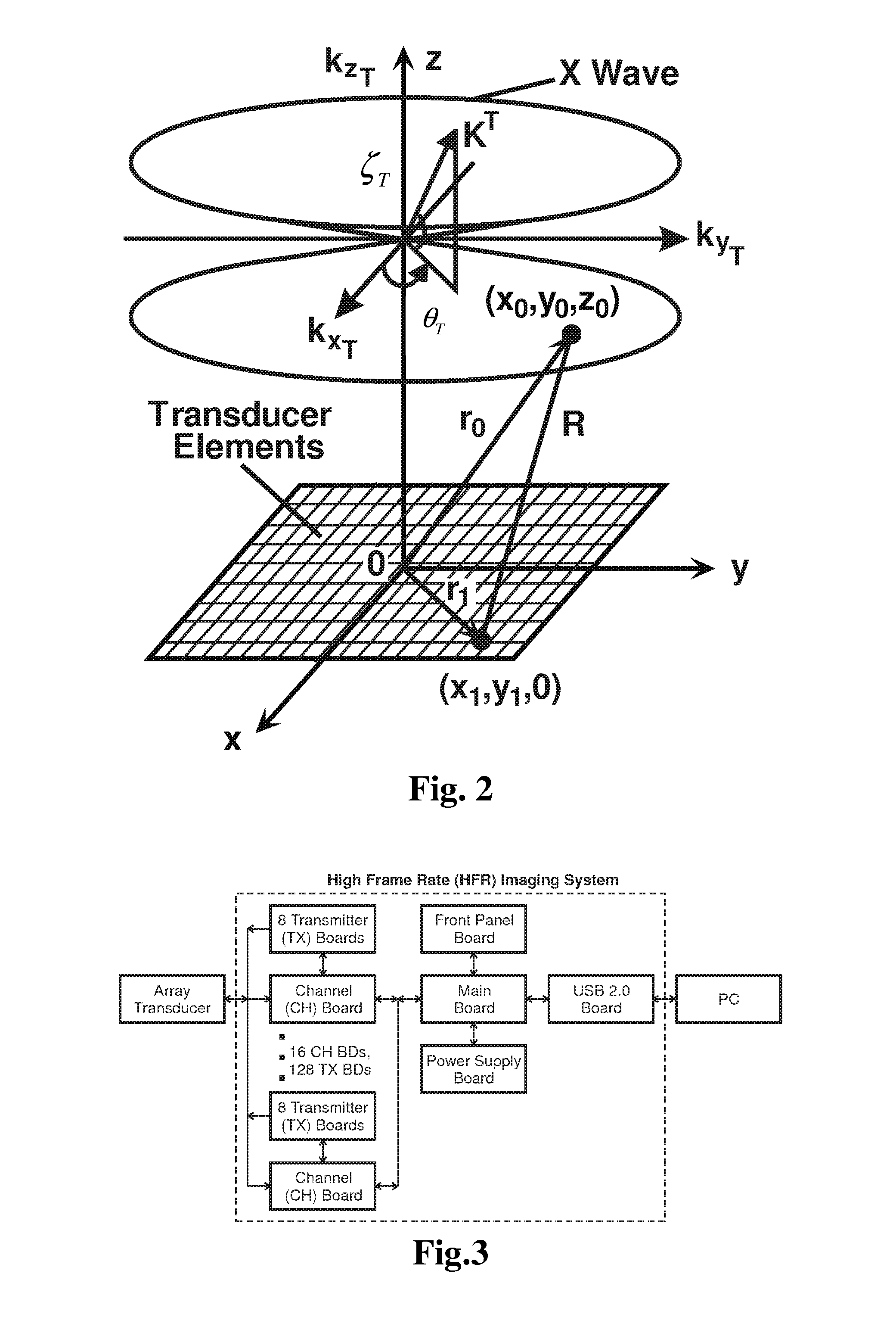
[0038]I.A. Theoretical Preliminaries
[0039]To understand the method of limited-diffraction array beam imaging with square-wave aperture weightings, it is helpful to summarize briefly the extended HFR imaging method and relate it to the X wave theory [4]-[8] for completeness. From the theory, it is shown that the relationship that the limited-diffraction array beam aperture weightings [24]-[26] on echo signals are identical to the 2D Fourier transform of the signals on the same transducer aperture can be generalized to an arbitrary transmit beam. The theory also makes it clear that with the square-wave aperture weightings, the transmission scheme of an imager could be simplified from that of the traditional D&S method [38], i.e., in principle, only one or two transmitters are needed to implement a 3D ultrasound imaging system. In addition, the square-wave aperture-weighting concept can also be...
PUM
 Abstract
Description
Claims
Application Information