
Method for treating slag flowing from a metallurgical vessel and a device for carrying out said method

Inactive Publication Date: 2013-07-30
TECHCOM
View PDF1 Cites 0 Cited by
  • Summary
  • Abstract
  • Description
  • Claims
  • Application Information

AI Technical Summary

Benefits of technology

The proposed unit allows for slag processing directly from the start of falling to the end, without the need for a metallurgical tank. The unit can also crush any parts of slag that need to be removed from the tank. This eliminates the need for additional equipment and reduces costs.

Problems solved by technology

Slag is a metallurgical product without which a quality hot metal can not be obtained.
While capacities of metallurgical units increase, an engineering task for arrangement of high-performance removal and processing of slags turned into a serious problem.
1) There are no technical solutions of slag processing after its leaving a metallurgical unit (tank) in the method;
2) In addition to the essential disadvantage mentioned the method implementation requires expensive stock of equipment, pots and slag cars;
The process of slag removal often restrains the capacity of a metallurgical unit.
The following essential disadvantages are inherent to the known method: firstly, arrangement of slag removal with appropriate equipment and its maintenance are required; secondly, slag removal takes a good deal of time as the processes to drain molten slag and to remove hardened slag are separated; thirdly, heavy-load conditions for workers engaged in collection and removal of solid slag.
An essential disadvantage is inherent to the known method: combining the operations of slag draining, hardening and crushing in the method causes intensive pickup of molten slag on some equipment parts of the unit used to implement the method.
The method can be implemented aside from the metallurgical unit what in some degree leads to the specified disadvantages of the method using pots for slag draining.

Method used


Image

  • Method for treating slag flowing from a metallurgical vessel and a device for carrying out said method
  • Method for treating slag flowing from a metallurgical vessel and a device for carrying out said method
  • Method for treating slag flowing from a metallurgical vessel and a device for carrying out said method

Examples


Embodiment Construction

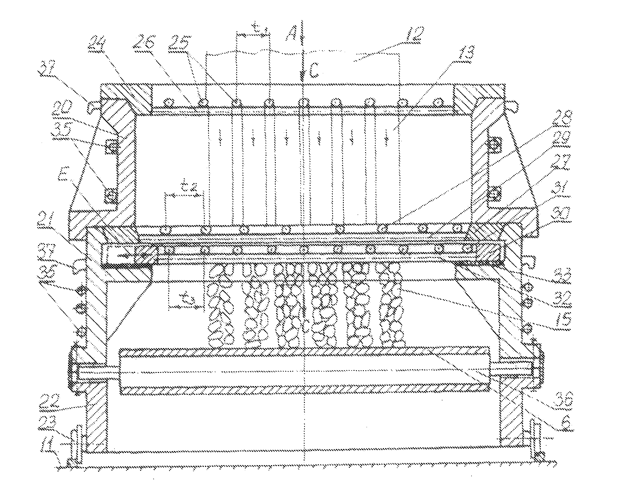
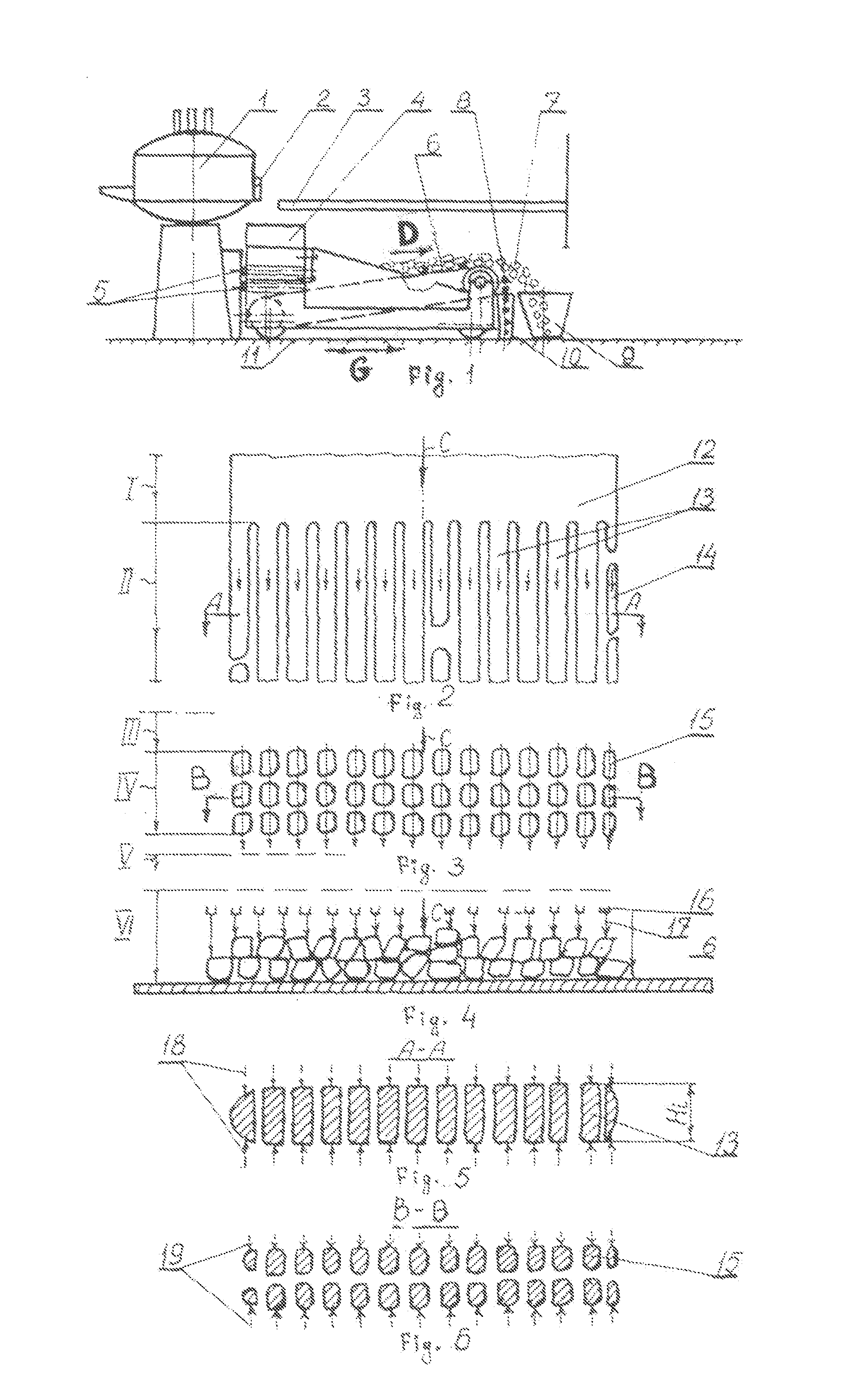
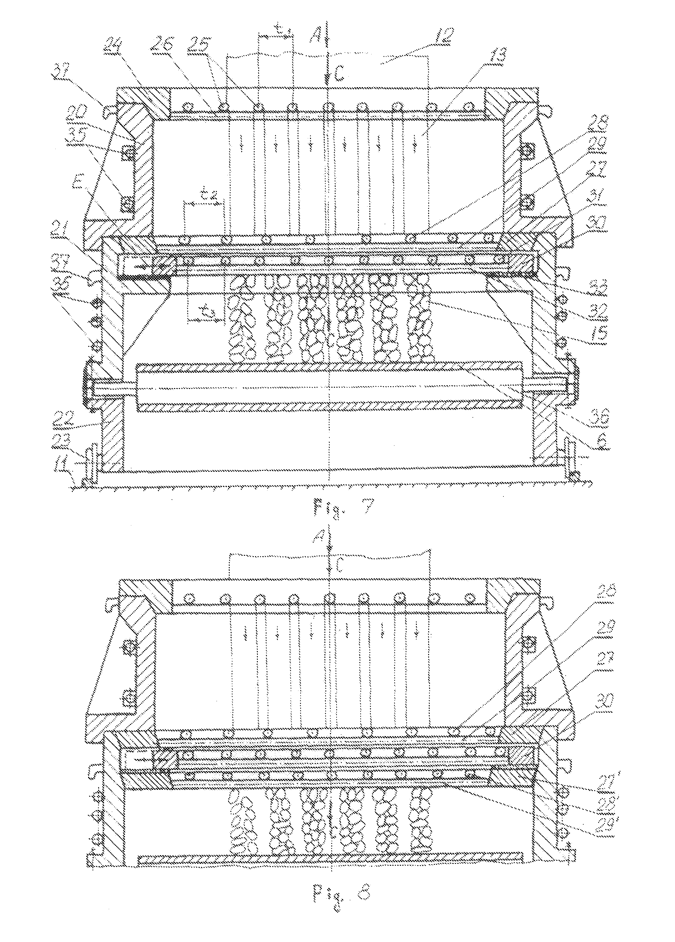
[0033]The specified technical solution is provided due to the fact that according to the invention the unit comprising the top grids includes at least three top grids installed horizontally and located one above another, one of which can be back-and-forth moved in the horizontal direction. Besides the upper grid is fixed and separated from other grids by space, where a coolant shall be supplied to; the lower grid is also fixed and the grid next to it is provided with back-and-forth moving drive and separated from the conveyor belt by space, where the coolant shall be supplied to, and as a whole all specified grids are installed in a split-type body which can be moved to / from the metallurgical tank. The conveyor belt is made profiled (that is thickened in comparison with the conveyor belt itself and with the tanks inside the belt body) and comes into contact with the cylindrical roll. Moreover the conveyor / profiled belt, its moving drive and the roll are installed on the specified bo...


PUM

PropertyMeasurementUnit
Flow rateaaaaaaaaaa

Abstract

A steel production method in the steel and iron industry involves dividing a vertically falling solid slag stream which flows from a steelmaking furnace into individual streams, forcedly cooling the individual streams, dividing the individual streams into parts by cutting across the movement thereof, forcedly cooling the parts and transferring them to a belt conveyor on which the separate parts are forcedly cooled and transported away from the vessel. A shaped conveyor belt, on which the slag parts are crushed by means of a cylindrical roll, is used for additional crushing.

Description

[0001]Applicants claim priority on the Russian Federation Application No. 2007125270 filed Apr. 7, 2007 and this is a Rule 371 application based on PCT Application No. PCT / IB2008 / 001755 filed on Jul. 3, 2008.BACKGROUND OF THE INVENTION[0002]The invention relates to metallurgy industry and can be used for processing of metallurgical slags.[0003]Slag is a metallurgical product without which a quality hot metal can not be obtained.[0004]Despite the whole range and purposes of slags formed during metallurgical production the necessity to remove slags separately from metal and their processing are the common thing for all metallurgical processes.[0005]While capacities of metallurgical units increase, an engineering task for arrangement of high-performance removal and processing of slags turned into a serious problem.[0006]A method of slag removal from metallurgical tanks by means of a pot is known [refer to, for example, I. Yu. Zinnurov et al. “Ways of Solving the Problem of Slag Removal...

Claims


Application Information

Patent Timeline
IPC IPC(8): C22B7/04B22F9/04
CPCC04B5/00C21B3/08C21B2400/024C21B2400/026C21B2400/06
Inventor SCHUMACHER, EDGARFRANZKY, RENATASCHUMACHER, SAGADATCHLOPONIN, VIKTOR NIKOLAEVICHFARMANOV, ALEXANDER KASYMOVICHKOSTIN, ANATOLIJ SERGEEVICHBELITCHENKO, ANATOLIJ KONSTANTINOWITCHJUDIN, ANDREY VASILEVITSCHSAVJUK, ALEKSANDER NIKOLAEVICHBOGDANOV, NIKOLAY ALEXANDROVITCHSCHUMACHER, EWALD ANTONOVICH
Owner TECHCOM
Features
  • Generate Ideas
  • Intellectual Property
  • Life Sciences
  • Materials
  • Tech Scout
  • Unparalleled Data Quality
  • Higher Quality Content
  • 60% Fewer Hallucinations
Learn More