Low pass filter circuit

a filter circuit and low-pass technology, applied in the field of low-pass filter circuits, can solve the problems of noise generation in the electric circuit, obvious undesirable, and noise generation in the sensing circuit, and achieve the effect of not being without limitations

Active Publication Date: 2013-07-30
NXP USA INC
View PDF7 Cites 9 Cited by
  • Summary
  • Abstract
  • Description
  • Claims
  • Application Information

AI Technical Summary

Problems solved by technology

It is well known that electrical circuits, such as sensing circuits, generate noise, an obviously undesirable but seemingly inevitable situation.
The above technique, while providing acceptable low pass and noise filtering performance is, however, not without its limitations.

Method used


Image

  • Low pass filter circuit
  • Low pass filter circuit
  • Low pass filter circuit

Examples


first embodiment

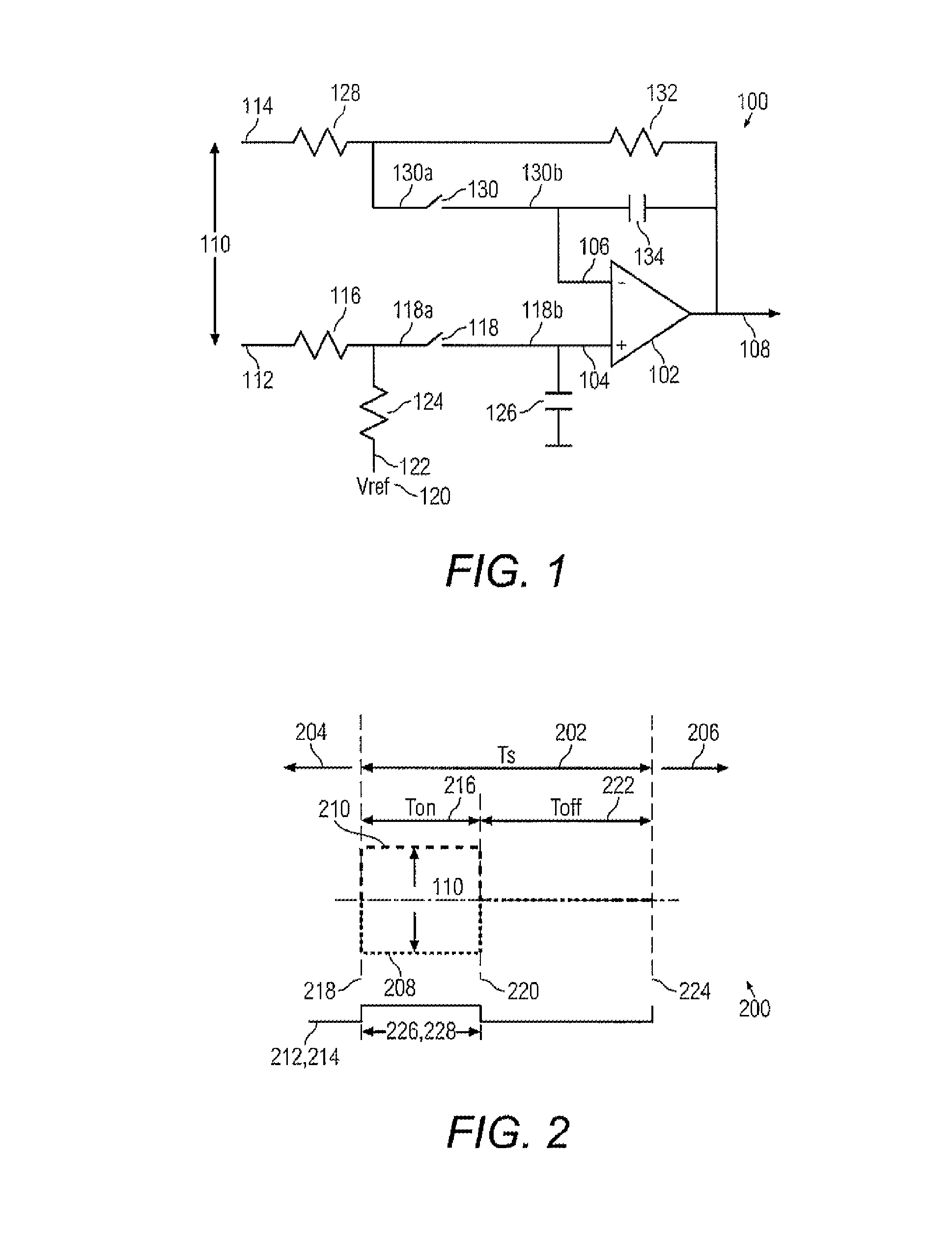
[0018]Referring now to FIG. 1, a low pass filter circuit 100 in accordance with the invention is illustrated. The low pass filter circuit 100 comprises an amplifier 102 having a first input 104 and a second input 106. In the embodiment of FIG. 1, the first input 104 is on a non-inverting summing node of the amplifier 102 and the second input 106 is on an inverting summing node of the amplifier 102. The amplifier 102 is a single-ended output amplifier, having an output 108. A differential signal 110 is provided to the first and second amplifier inputs 104, 106 on first and second lines 112, 114, respectively. The first line 112 is connected to the amplifier first input 104 through a first resistor 116 and a first switch 118. A reference voltage supply 120 is also connected to the amplifier first input 104 with a first voltage supply line 122 by way of a second resistor 124. As shown in FIG. 1, the first and second resistor 116, 124 are connected to an input terminal 118a of the switc...

second embodiment

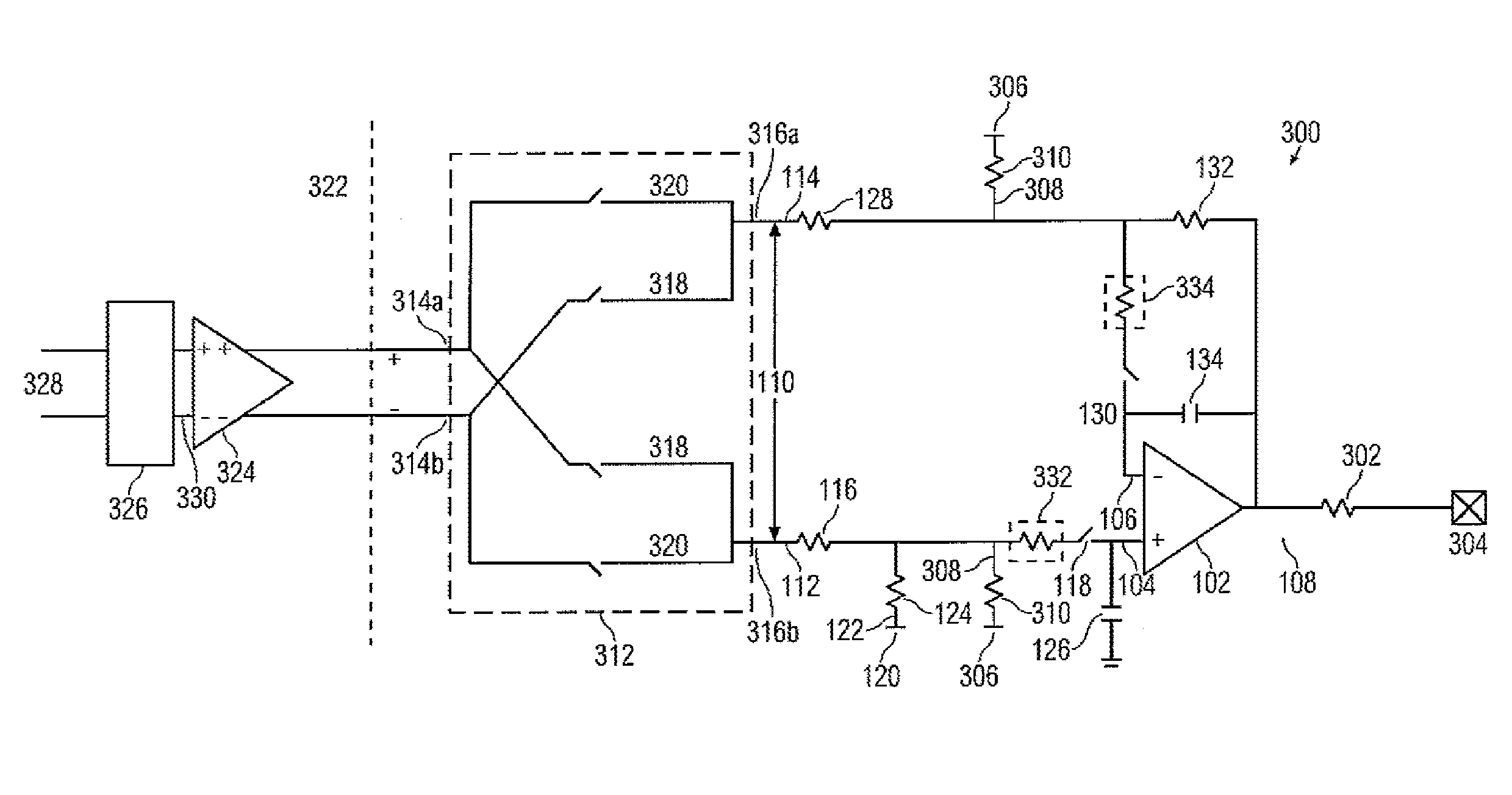
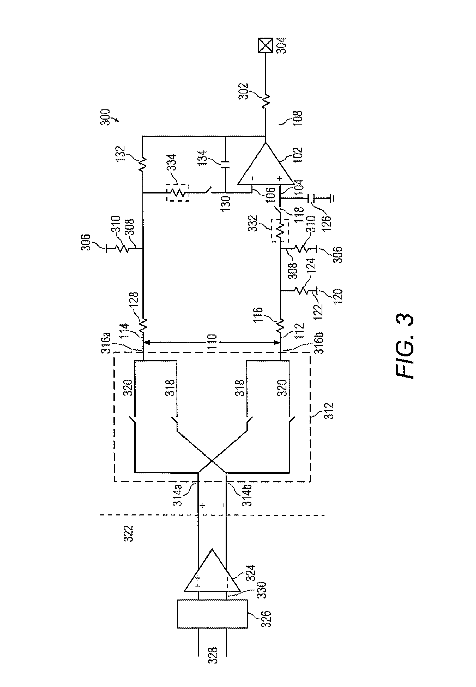
[0043]Turning now to FIG. 3, a low pass filter circuit 300 in accordance with the invention is illustrated. Many of the components of the circuit 300 of FIG. 3 operate in a manner identical with corresponding components in the circuit 100 of FIG. 1. Such components are identified with the same reference numerals as the corresponding components in FIG. 1, and a detailed discussion of these components is not repeated. However, in summary, the circuit 300 is provided with an amplifier 102 for receiving a differential input signal 110 on the first and second lines 112, 114. Circuit 300 also provides a single-ended output 108 of the amplifier 102. However, in the circuit 300, an output resistance 302 may optionally be provided for connection at output terminal 304 to another circuit (not illustrated), in which the output resistance 302 may act as a resistance in a RC filter of the other circuit. Use of a subsequent RC filter, of which resistor 302 constitutes the resistance in combinatio...


PUM


Abstract

A low pass filter circuit includes an amplifier having a single-ended output. A first line and a second line are arranged to receive a differential signal. A first switch selectively connects the first line to a first input of the amplifier in a first cycle of operation having a first observation window. A second switch selectively connects the second line to a second input of the amplifier in a second cycle of operation having a second observation window that is at least partially coincident with the first observation window. A signal measuring stage that is supplied with a modulated input signal generates the differential signal. The signal measuring state has an input switch to reverse a polarity of the differential signal applied to the first and second lines of the low pass filter circuit.

Description

BACKGROUND OF THE INVENTION[0001]The present invention relates to electronic circuits and more particularly to a low pass filter circuit.[0002]It is well known that electrical circuits, such as sensing circuits, generate noise, an obviously undesirable but seemingly inevitable situation. Significant efforts have been undertaken either to reduce or to mitigate the undesirable effects that noise can cause in an electrical circuit. One way is to with an amplifying and filtering circuit that has a single-ended input and a single-ended output. This circuit uses an amplifier that receives a single-ended input signal, implements a sample and hold operation alternately on each of the amplifier inputs achieved by alternately switching switches on each of the amplifier inputs. When a first switch on one of the amplifier inputs is closed, the amplifying and filtering circuit samples a first signal having a noise component. The first switch is opened and a second switch on a second one of the a...

Claims


Application Information

Patent Timeline
Patent Type & Authority Patents(United States)
IPC IPC(8): H03B1/00
CPCH03H19/00
Inventor BECKWITH, JOEL C.MIJUSKOVIC, DEJAN
Owner NXP USA INC
Why Eureka
Try Eureka