
Engagement chain

a technology of engagement chain and buckling force, which is applied in the direction of chain elements, lifting devices, hoisting equipment, etc., can solve the problems of buckling strength and difficulty in ensuring rigidity of the pair of engagement chains engaging with each other, and achieve stable forward and backward driving of work, improved buckling strength of the pair of engagement chains, and simplified system structure

Inactive Publication Date: 2013-08-06
TSUBAKIMOTO CHAIN CO
View PDF17 Cites 11 Cited by
  • Summary
  • Abstract
  • Description
  • Claims
  • Application Information

AI Technical Summary

Benefits of technology

The solution improves buckling strength, eliminates backlash, and ensures stable operation by maintaining a straight chain engagement attitude, reducing noise and improving work positioning accuracy, while simplifying the system structure and enhancing durability.

Problems solved by technology

One problem with such prior art engagement chains, however, is a pair of engagement chains engaging with each other inevitably causes backlash therein due to gaps between engaging portions and between bushes and connecting pins when the engaging portions of link plates are engaged, meaning it is difficult to assure rigidity of the pair of engagement chains engaging with each other and the buckling strength of the pair of engagement chains may possibly drop.

Method used


Image

  • Engagement chain
  • Engagement chain
  • Engagement chain

Examples


first embodiment

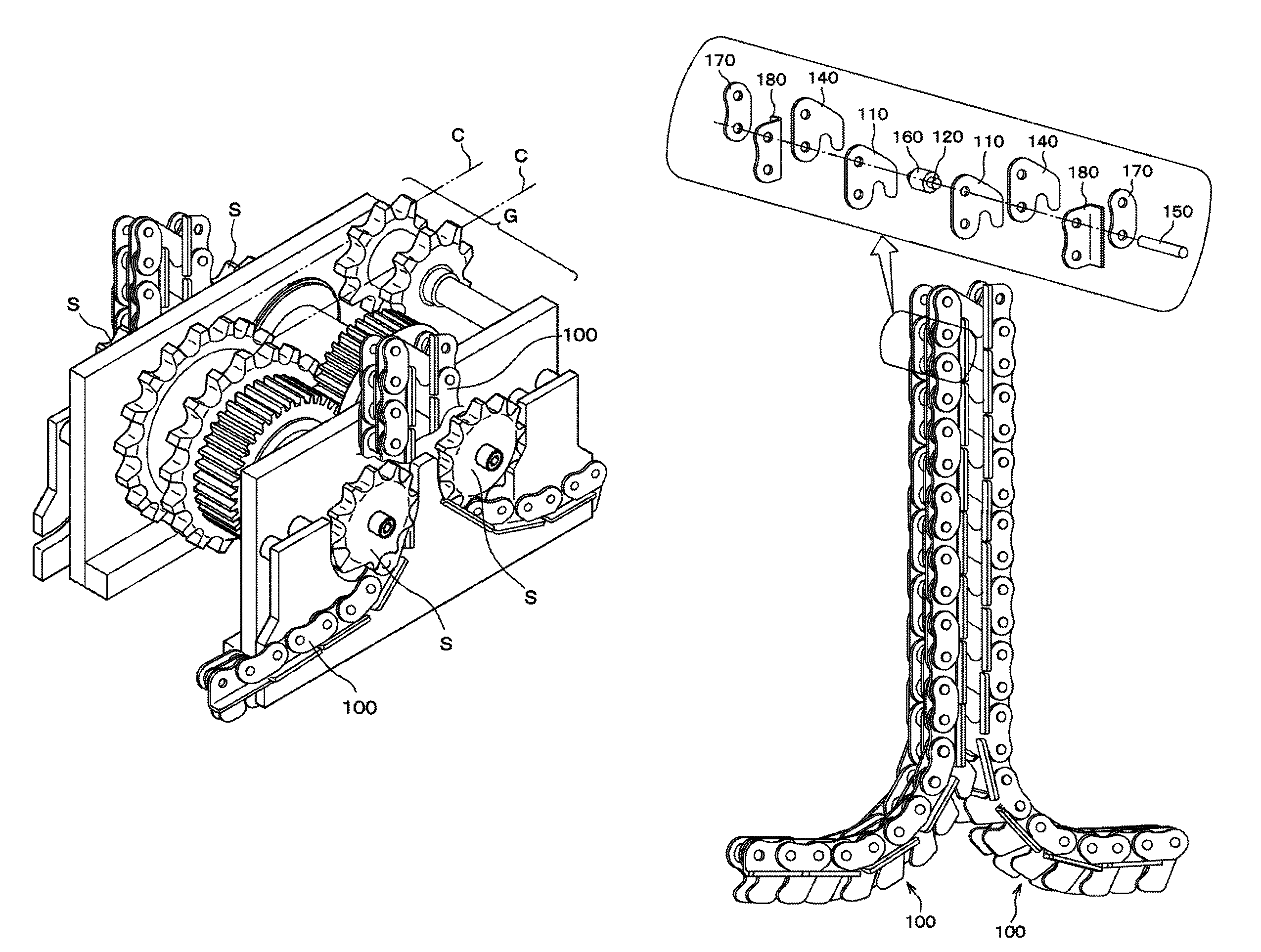
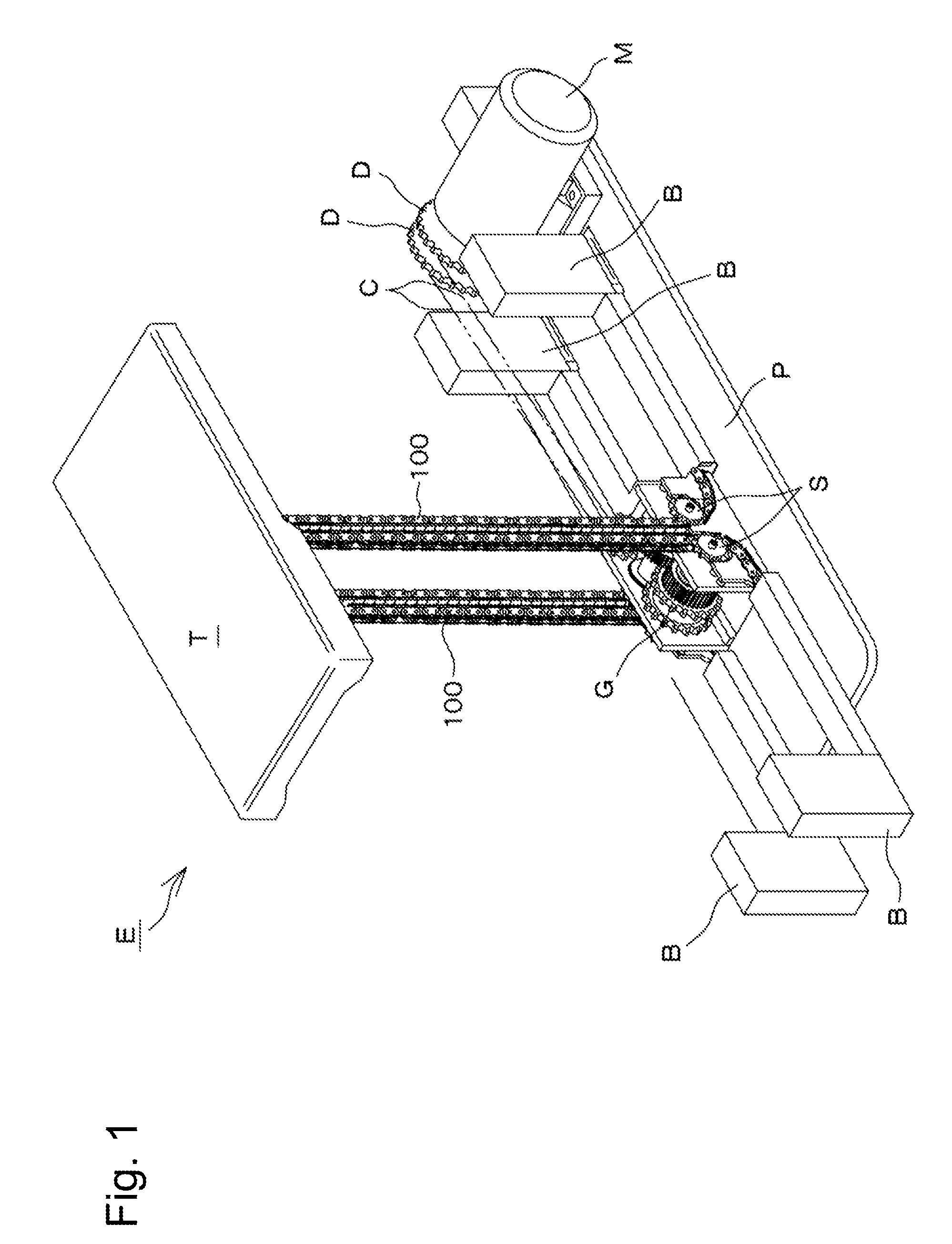
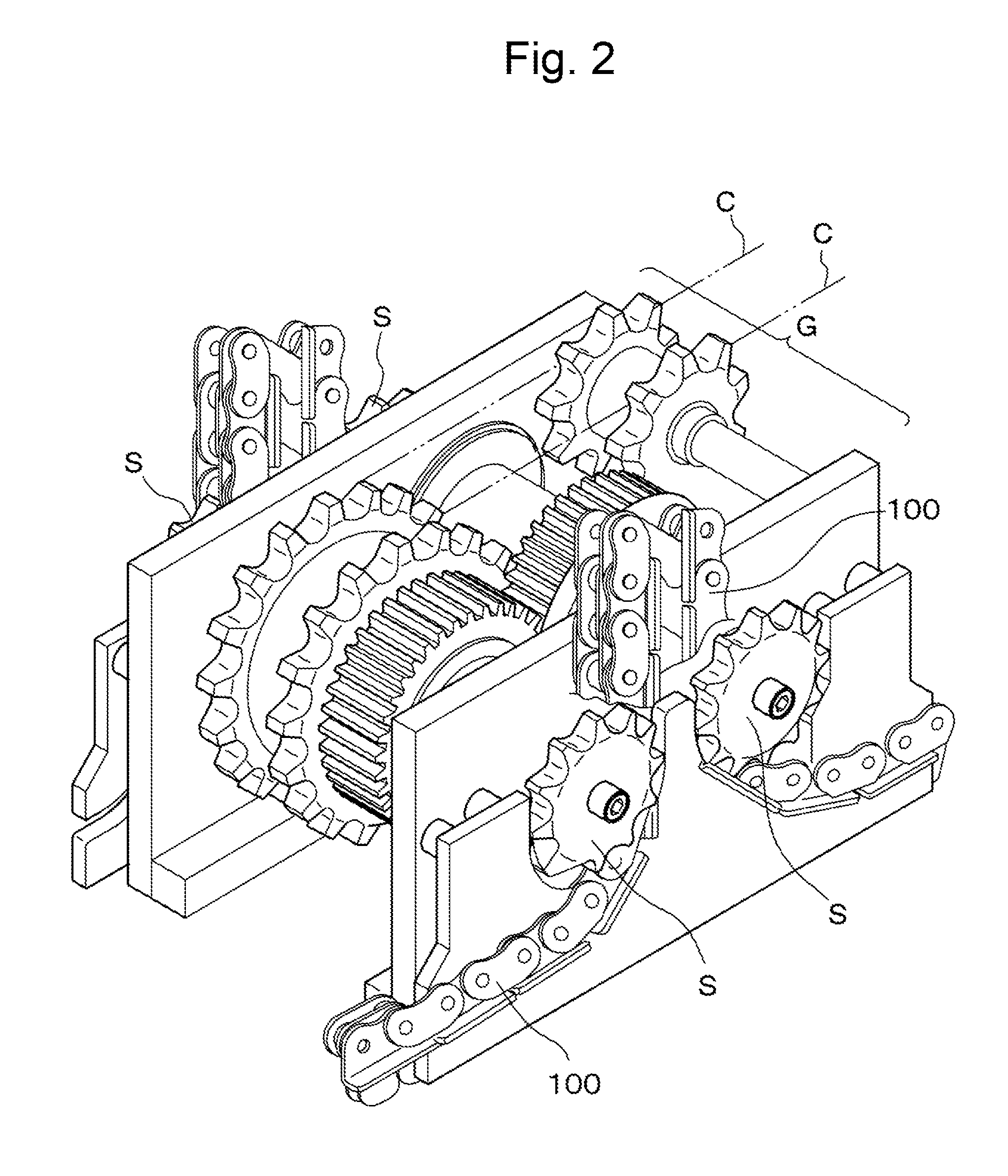
[0020]The engagement chain 100 of one embodiment of the invention will be explained with reference to the drawings. Here, FIG. 1 shows a mode of use of the engagement chain of a first embodiment of the invention, FIG. 2 is a partially enlarged view of the driving sprockets and their neighborhood shown in FIG. 1, FIG. 3 is a perspective view showing the engagement chains, FIG. 4 is a partially enlarged view showing the engagement chains and FIG. 5 is a partial section view showing the engagement chain.

[0021]As shown in FIG. 1, the pairs of engagement chains 100 of the first embodiment of the invention are used by being incorporated into an engagement chain type driving system E installed so as to be stationary on a working floor surface. The system is installed in order to lift up and down a lift table T carrying a heavy load in parallel with the installation surface.

[0022]The engagement chain type driving system E described above has, as its basic system structure, a base plate P in...


PUM


Abstract

The invention provides a pair of engagement chains which has inner tooth plates, bushes, outer tooth plates and connecting pins and is integrated by engaging hook portions of the inner tooth plates and hook portions of the outer tooth plates and is branched by disengaging the hook portions of the inner tooth plates and the hook portions of the outer tooth plates. The pair of engagement chains further includes inflection restricted plates having inflection restricted surfaces and inflection restricting plates having inflection restricting portions that are connected on the both ends of the connecting pins.

Description

CROSS REFERENCE TO RELATED APPLICATIONS[0001]This application claims the foreign priority benefit under Title 35, United States Code, §119 (a)-(d) of Japanese Patent Application No. 2009-254156, filed on Nov. 5, 2009 in the Japan Patent Office, the disclosure of which is herein incorporated by reference in its entirety.BACKGROUND OF THE INVENTION[0002]1. Field of the Invention[0003]The present invention relates to an engagement chain incorporated into a driving system for use in a manufacturing facility in various manufacturing fields, a transfer facility in transportation fields, a nursing care facility in health-care and welfare fields, a stage facility in performing art fields and the like to vertically lift works with respect to an installation surface. More particularly, the present invention relates to an engagement chain for a driving system with improved buckling strength.[0004]2. Related Art[0005]One example of a driving system currently known in the art is a lift system fo...

Claims


Application Information

Patent Timeline
Patent Type & Authority Patents(United States)
IPC IPC(8): B66D1/30
CPCF16G13/20B66F13/005B66F3/06B66F7/0666
Inventor YAOI, KIYOTAKEOITAKE, MICHIO
Owner TSUBAKIMOTO CHAIN CO
Learn More