Illuminant device and manufacturing method of lamp holder

a technology of lamp holder and manufacturing method, which is applied in the direction of semiconductor devices for light sources, lighting and heating apparatus, and light support devices, etc., can solve the problems of manufacturing and cost difficulties, and achieve the effect of reducing manufacturing costs and effective easy-to-produce processes

Inactive Publication Date: 2013-08-06
COOLER MASTER DEVELOPMENT CORP
View PDF5 Cites 4 Cited by
  • Summary
  • Abstract
  • Description
  • Claims
  • Application Information

AI Technical Summary

Benefits of technology

[0007]It is an object of the present invention to provide an illuminant device, the illuminant device has advantages of easily manufacture, lower manufacturing cost, light and high insulating property.
[0008]It is another object of the present invention to provide a manufacturing method of a lamp holder which can easily productive processes and lower manufacturing cost.
[0011]In the present invention, the circuit board of the power driving unit is directly assembled to the MCPCB, thereby can effectively easily productive processes and lower manufacturing cost.

Problems solved by technology

This increases productive processes, the difficulty of manufacturing and cost.

Method used


Image

  • Illuminant device and manufacturing method of lamp holder
  • Illuminant device and manufacturing method of lamp holder
  • Illuminant device and manufacturing method of lamp holder

Examples


Embodiment Construction

[0030]Reference will now be made in detail to the present embodiments of the invention, examples of which are illustrated in the accompanying drawings. Wherever possible, the same reference numbers are used in the drawings and the description to refer to the same or like parts.

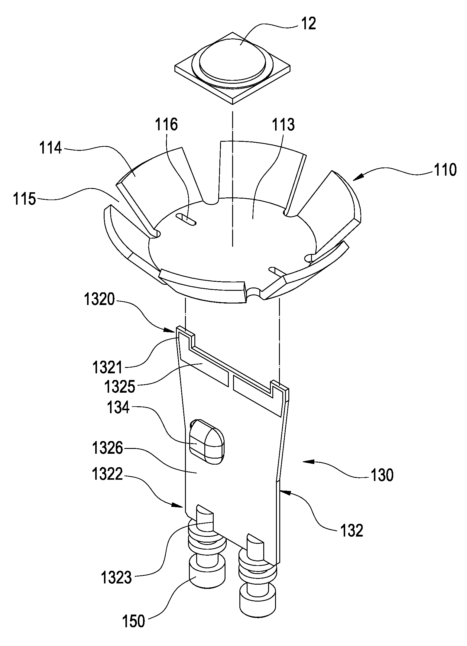
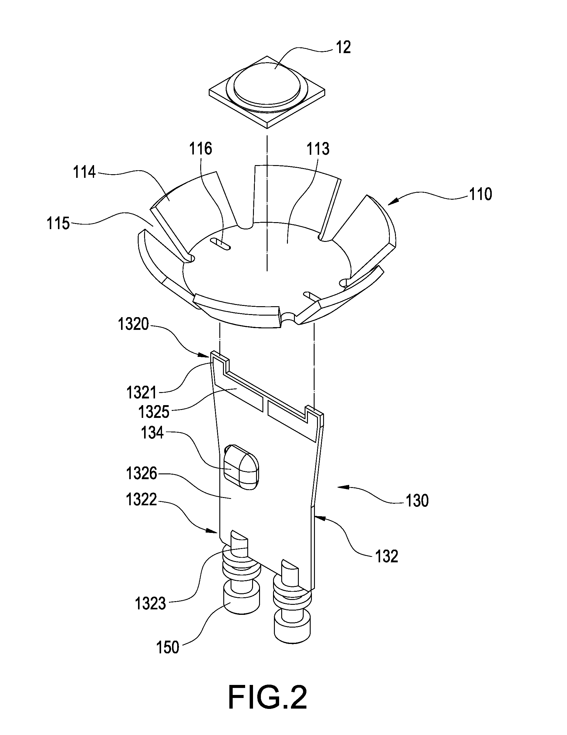
[0031]Reference is made to FIG. 2, FIG. 3 and FIG. 4, which are respectively a partially exploded view, a partially assembled view and a cross-sectional view of an illuminant device according to a first preferred embodiment of present invention. In this embodiment, the illuminant 10 is, for example, a GU10 lamp. However, in the practical application, the illuminant device 10 may be PAR series lamp, A19, A20, A60, G30 or other type lamps. The illuminant device 10 includes a lamp holder 11 and at least an illuminant element 12. The lamp holder 11 includes a metal core printed circuit board (MCPCB) 110, a power driving unit 130 and a housing 140.

[0032]The MCPCB 110 has better thermal conductive and is provided wi...


PUM

PropertyMeasurementUnit
circumferenceaaaaaaaaaa
optical axisaaaaaaaaaa
thermoplasticityaaaaaaaaaa

Abstract

An illuminant device includes at least an illuminant element and a lamp holder including a housing, a metal core printed circuit board (MCPCB) and a power-driving unit. The housing includes a first side and a second side opposite to the first side. The MCPCB is disposed on the first side of the housing and includes a base and a plurality of extending parts extended from the circumference of base in a bending forming manner and spaced from each other. The base has a plurality of holes, the extending parts are embedded within the housing, and the illuminant element is mounted on the base. The power-driving unit includes a circuit board, and a first end of the circuit board has a plurality of posts. The posts are respectively penetrated the holes and electrically connected to the MCPCB. In addition, a manufacturing method of the lamp holder is disclosed.

Description

BACKGROUND OF THE INVENTION[0001]1. Field of the Invention[0002]The present invention relates to an illuminant device, especially to an illuminant device with high thermal conductivity coefficient and insulating property and uses light emitting diodes as light source.[0003]2. Description of Prior Art[0004]Light emitting diodes (LEDs) have the advantages of small volume, long lifetime, difficulty damage, without mercury and lower power consumption. They are gradually replacing the fluorescent tubes and incandescent lamps and widely used in indoor or outdoor lighting and decorative lighting.[0005]Reference is made to FIG. 1, which is a cross-sectional view of a conventional LED lamp. The LED lamp includes a housing 50, a circuit board 52, a plurality of LEDs 54, a conductive connector 56, a shell 58 and a power driving unit 59. The housing 50 is a hollow body and has a plurality of fins 51 radially extended from a circumferential wall and physically connected thereon, thereby the heat...

Claims


Application Information

Patent Timeline
Patent Type & Authority Patents(United States)
IPC IPC(8): F21V1/00F21S4/00H01J5/50H01J5/48F21V11/00F21V21/00
CPCF21V29/004F21V5/04F21V5/045F21V7/0091F21V17/005F21V17/164F21V23/006F21K9/1375F21V29/507F21V29/75F21V29/773F21V29/78F21V3/0445Y10T29/49126F21Y2101/02F21Y2105/001F21K9/23F21Y2105/10F21Y2115/10F21V3/0625F21V29/70
Inventor DUAN, QIANG-FEI
Owner COOLER MASTER DEVELOPMENT CORP
Why Eureka
Try Eureka