Work vehicle and method of controlling the same

a technology of work instruments and clutches, applied in the field of work vehicles, can solve the problems of reducing the action speed reducing reducing the efficiency of the work instrument, so as to inhibit the reduction of the life duration of the lock-up clutch, fuel consumption can be enhanced, and torque transmission efficiency can be further enhanced

Active Publication Date: 2013-08-06
KOMATSU LTD
View PDF10 Cites 7 Cited by
  • Summary
  • Abstract
  • Description
  • Claims
  • Application Information

AI Technical Summary

Benefits of technology

[0006]It is an object of the present invention to appropriately distribute driving force from an engine to both of a drive unit and a work instrument at a higher transmission efficiency when a work vehicle starts moving in order to enhance fuel consumption, and simultaneously, inhibit delay in the engine speed increase and reduction in the action speed of the work instrument.
[0020]According to the method of controlling a work vehicle of the seventh aspect of the present invention, the lock-up slippage control is executed for switching the lock-up clutch into the slippage state when the vehicle starts moving. Accordingly, torque transmission efficiency can be further enhanced than that obtained where the torqcon state is kept for a long period of time when the vehicle starts moving. Therefore, fuel consumption can be enhanced when the vehicle starts moving. Meanwhile, work vehicles may execute a work using the work instrument immediately after starting moving. In this case, increase in the engine speed is delayed when the large amount of torque is transmitted by the lock-up clutch. For example, the large amount of torque is transmitted by the lock-up clutch when the slippage amount of the lock-up clutch is small. Therefore, load acting on the engine as well as load acting on the work instrument is increased, and increase in the engine speed is delayed. In this case, increase in the rotation speed of the hydraulic pump is also delayed. Therefore, a problem is caused that an action of the work instrument is delayed. In view of the above, in the method of controlling a work vehicle according to the seventh aspect of the present invention, the lock-up hydraulic pressure is controlled based on the work instrument load information during execution of the lock-up slippage control. Therefore, the amount of torque to be transmitted by the lock-up clutch can be controlled in consideration of load acting on the work instrument. Accordingly, it is possible to enhance fuel consumption when the vehicle starts moving, and simultaneously, inhibit delay in engine speed increase and reduction in the action speed of the work instrument.

Problems solved by technology

Due to this, such a work vehicle has a drawback of inefficient fuel consumption when starting moving.
When the driving force from the engine is not herein appropriately distributed, a variety of problems may be caused that include delay in engine speed increase, reduction in the action speed of the work instrument and etc.
In this case, increase in the engine speed is delayed when the large amount of torque is transmitted by the lock-up clutch.
Therefore, load acting on the engine as well as load acting on the work instrument is increased, and increase in the engine speed is delayed.
In this case, increase in the rotation speed of the hydraulic pump is also delayed.
Therefore, a problem is caused that an action of the work instrument is delayed.

Method used


Image

  • Work vehicle and method of controlling the same
  • Work vehicle and method of controlling the same
  • Work vehicle and method of controlling the same

Examples


Embodiment Construction

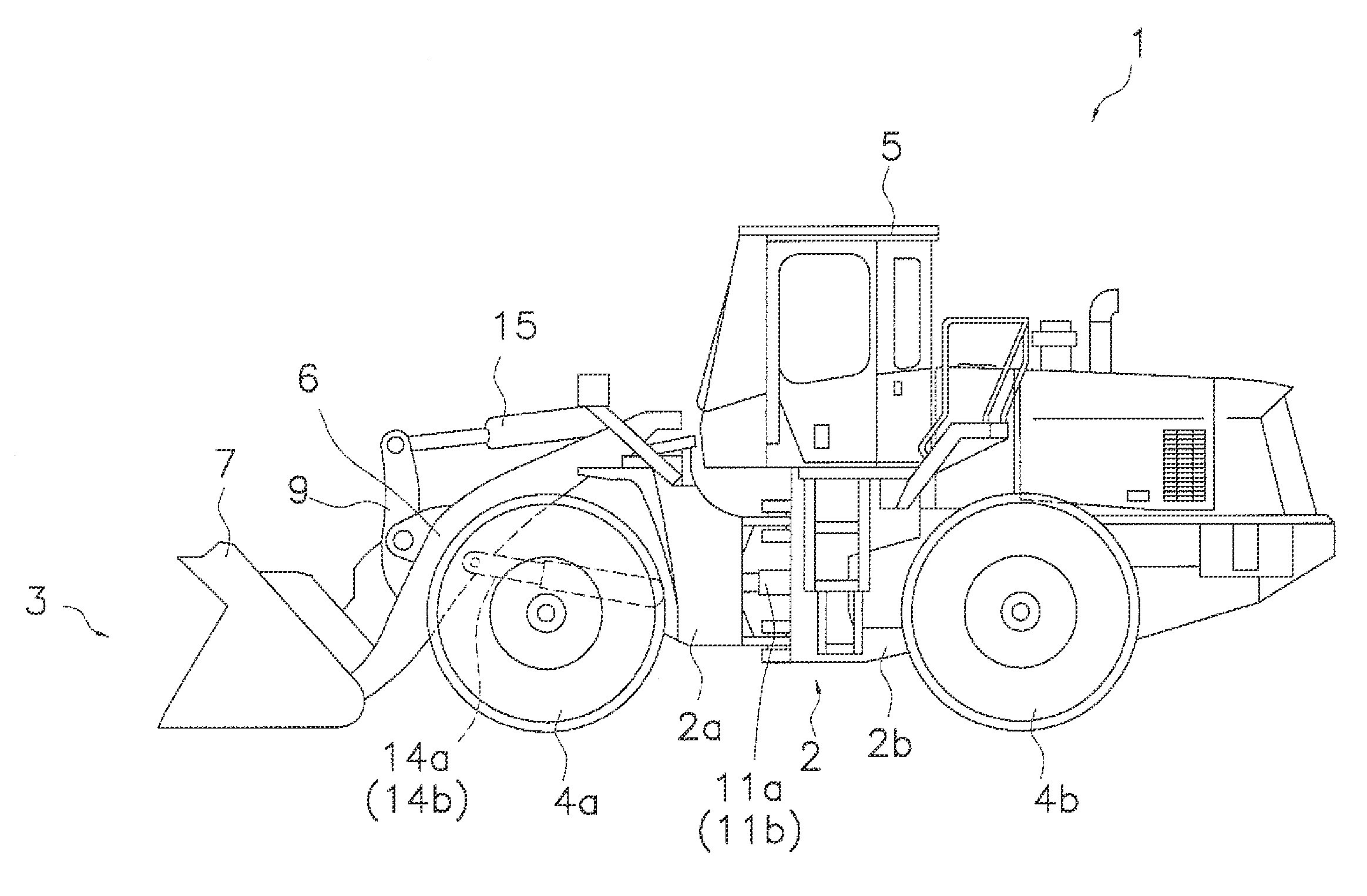
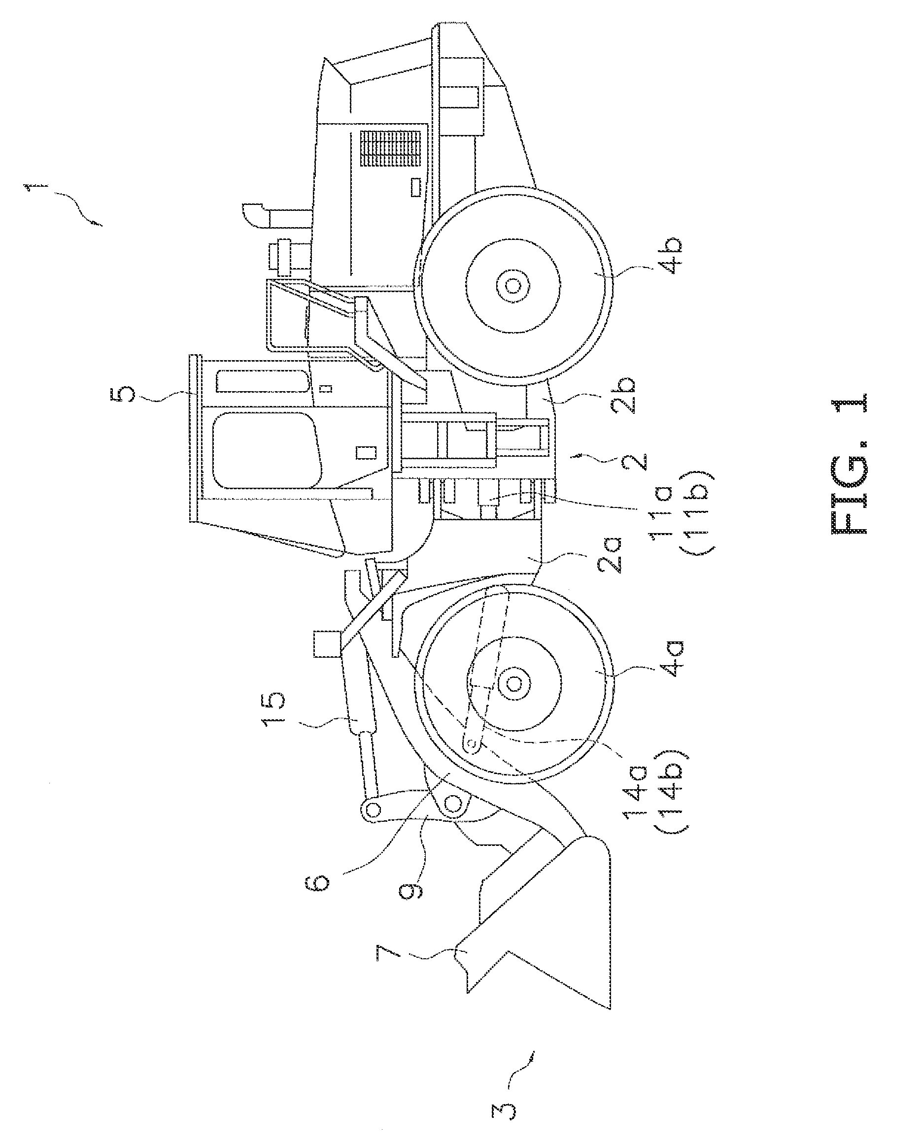
[0027]FIGS. 1 and 2 illustrate a work vehicle 1 according to an exemplary embodiment of the present invention. FIG. 1 is an external view of the work vehicle 1, while FIG. 2 is a schematic configuration view of the work vehicle 1. The work vehicle 1 is a wheel loader. The work vehicle 1 can be self-propelled by rotational driving of front wheels 4a and rear wheels 4b. Further, the work vehicle 1 can perform a desired work using a work instrument 3.

[0028]As illustrated in FIG. 1, the work vehicle 1 includes a vehicle body frame 2, the work instrument 3, the front and rear wheels 4a and 4b and a cab 5.

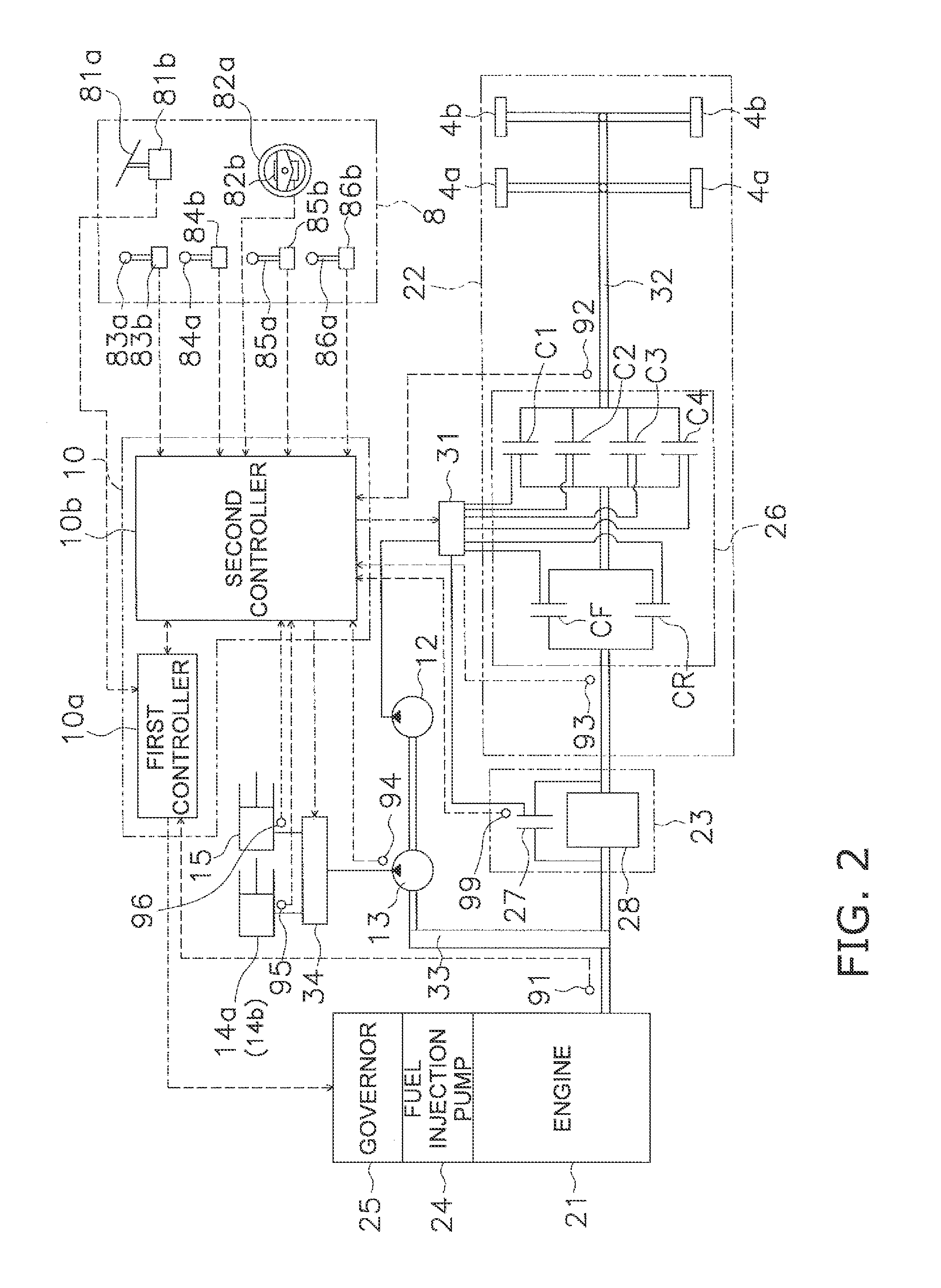
[0029]The vehicle body frame 2 includes a front vehicle body part 2a and a rear vehicle body part 2b. The front and rear vehicle body parts 2a and 2b are coupled to each other while being pivotable in a transverse (right-and-left) direction. A pair of steering cylinders 11a and 11b is provided astride the front and rear vehicle body parts 2a and 2b. The steering cylinders 11a and 11b are...


PUM


Abstract

In a work vehicle, a control unit is configured to control a lock-up hydraulic pressure for controlling switching of a lock-up clutch. The control unit is configured to execute a lock-up slippage control for switching the lock-up clutch into a slippage state when the work vehicle starts moving. The control unit is configured to control the lock-up hydraulic pressure based on work instrument load information, pertaining to a load of a work instrument during execution of the lock-up slippage control.

Description

CROSS-REFERENCE TO RELATED APPLICATIONS[0001]This application claims priority to Japanese Patent Application No. 2010-027272, filed on Feb. 10, 2010, the disclosure of which is hereby incorporated herein by reference in its entirety.TECHNICAL FIELD[0002]The present invention relates to a work vehicle and a method of controlling the same.BACKGROUND ART[0003]Some work vehicles such as the wheel loaders are embedded with a torque converter unit including a torque converter and a lock-up clutch. When the lock-up clutch is set to be in a decoupled state, the torque converter unit is configured to transmit driving force from an engine to a drive unit through the torque converter (this state will be hereinafter referred to as “a torqcon state”). When the lock-up clutch is set to be in a coupled state, by contrast, the torque converter unit is configured to transmit driving force from the engine to the drive unit through the lock-up clutch (this state will be hereinafter referred to as “a l...

Claims


Application Information

Patent Timeline
Patent Type & Authority Patents(United States)
IPC IPC(8): G06F17/00
CPCF16H61/143E02F9/202E02F9/2066E02F9/2253F16H59/18F16H59/44F16H2059/145F16H2061/145F16H2312/02
Inventor YAMAGUCHI, EIJIKUSE, TAKASHI
Owner KOMATSU LTD
Why Eureka
Try Eureka