
Fluid injector with auxiliary filling orifice

a technology of auxiliary filling and injector, which is applied in the direction of liquid fuel feeder, fuel injecting pump, machine/engine, etc., can solve the problems of elusive entire engine operating range, inability to provide a fuel injection system that can perform well, and excessive amount of undesirable emissions

Inactive Publication Date: 2013-08-13
CATERPILLAR INC
View PDF28 Cites 6 Cited by
  • Summary
  • Abstract
  • Description
  • Claims
  • Application Information

AI Technical Summary

Benefits of technology

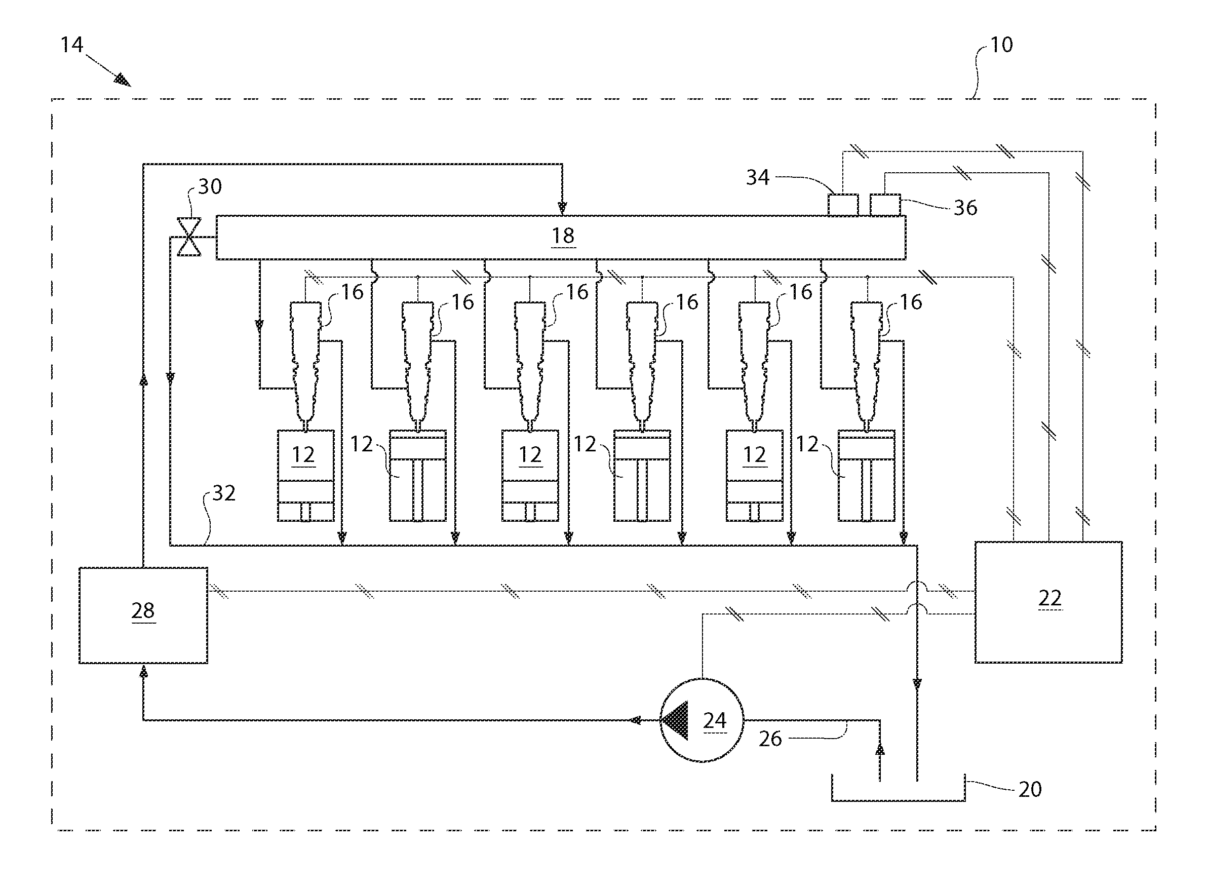
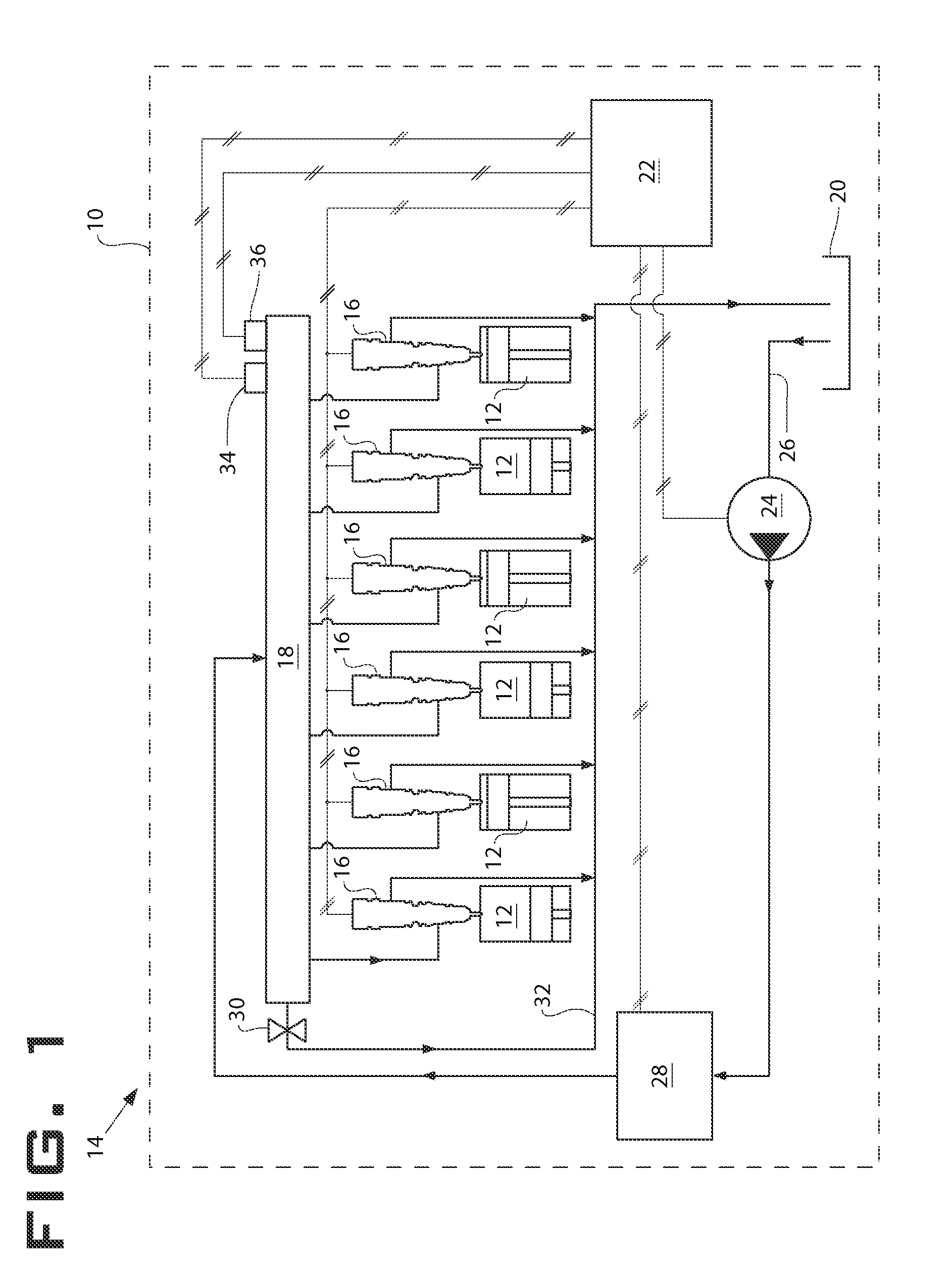
This patent describes a fluid injector and an internal combustion engine including a fuel system with multiple fuel injectors. The fluid injector includes a check needle that can block or partially open the nozzle outlet, and a control valve that can selectively allow fluid communication between the low pressure drain and the check needle control chamber. This allows for control of the check needle movement by selectively opening or closing the nozzle outlet. The patent also describes a method of operating the fuel injector with the check needle by supplying high pressure fuel to the nozzle chamber and the check needle control chamber, and selectively blocking or unblocking the fluid communication between the check needle control chamber and the low pressure drain. The technical effects of this patent include improved control of fuel injection and improved fuel system performance.

Problems solved by technology

However, it has also been observed that an injection strategy at one engine operating condition may decrease emissions at that particular operating condition, but actually produce an excessive amount of undesirable emissions at a different operating condition.
Providing a fuel injection system that can perform well with regard to all of these different parameters over an entire engine's operating range has proven to be elusive.
The use of a bypass conduit that feeds into the valve chamber and then the needle control chamber outlet has a drawback of inevitably affecting the start of injection.
Moreover, the valve and valve chamber required to facilitate the bypass conduit add cost and variability to the operation of the injector.

Method used


Image

  • Fluid injector with auxiliary filling orifice
  • Fluid injector with auxiliary filling orifice
  • Fluid injector with auxiliary filling orifice

Examples


first embodiment

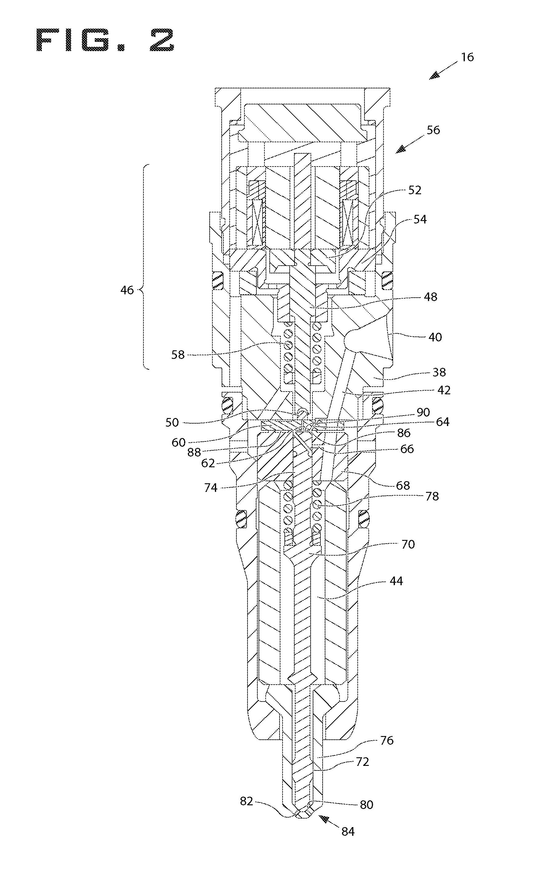
[0020]Referring now to FIG. 3, a detail (not to scale) of a first embodiment is shown. A check needle control chamber 86 is defined by a lower surface 88 of orifice plate 60, a distal surface 90 of the second end of check needle 70 and a portion 92 an interior surface of the upper check guide 68. First orifice 62, which may also be called an a-orifice, is in direct fluid communication with check needle control chamber 86. When injector 16 is not injecting fluid, valve member 50 rests atop orifice plate 60 and blocks first orifice 62. As will be explained in greater detail below, during injection, valve member 50 is at least partially out of contact with orifice plate 60 and fluid from check needle control chamber 86 is allowed to drain out of the first orifice 62 and ultimately out of injector 16.

[0021]In the embodiment shown in FIG. 3, orifice plate 60 also has a second orifice 64, which may also be called a z-orifice. Second orifice 64 is in direct fluid communication with check n...

second embodiment

[0031]Referring now to FIG. 4, a detail (not to scale) of a second embodiment is shown. A check needle control chamber 186 is defined, at least partially, by a lower surface 188 of orifice plate 160, a distal surface 190 of a second end 174 of check needle 170 and a portion 192 of an interior surface of the upper check guide 168. First orifice 162, which may also be called an a-orifice, is in direct fluid communication with check needle control chamber 186. In the embodiment shown, in FIG. 4, the orifice plate 160 includes a counter bore 167, which may further facilitate fluid communication between the first orifice 162 and the check needle control chamber 186. When fuel injector 16 is not injecting fluid, valve member 150 rests atop orifice plate 160 and blocks first orifice 162. During injection, valve member 150 is at least partially out of contact with orifice plate 160 and fluid from check needle control chamber 186 is allowed to drain through counter bore 167 and the first ori...


PUM


Abstract

A common rail single fluid injection system including fuel injectors with the ability to produce multiple injection rate shapes. This is accomplished by including auxiliary filling orifices which selectively provide pressurized fluid to the check needle control chamber during injection events. In so doing, the speed and movement of the check needle is manipulated and differing injection rates may be achieved.

Description

TECHNICAL FIELD[0001]The present disclosure relates generally to a single fluid fuel injection system, and more particularly to fuel injection systems with an auxiliary filling orifice.BACKGROUND[0002]Engines, including diesel engines, gasoline engines, natural gas engines, and other engines known in the art, exhaust a complex mixture of combustion related constituents. The constituents may be gaseous and solid material, which include nitrous oxides (NOx) and particulate matter. Due to increased attention on the environment, exhaust emission standards have become more stringent and the amount of NOx and particulate matter emitted from an engine may be regulated depending on the type of engine, size of engine, and / or class of engine.[0003]Engineers have come to recognize that undesirable engine emissions, such as NOx, particulate matter, and unburnt hydrocarbons, can be reduced across an engine's operating range with fuel injection systems with maximum flexibility in controlling inje...

Claims


Application Information

Patent Timeline
Patent Type & Authority Patents(United States)
IPC IPC(8): F02M69/04F02M43/00
CPCF02M45/12F02M47/027F02M63/0036
Inventor FANG, DIANQIZHANG, LINLEWIS, STEPHEN ROBERTXU, ZHENLONGMANUBOLU, AVINASH R.LAKHAPATI, SHRIPRASAD G.HANSON, CHRISTOPHER D.
Owner CATERPILLAR INC
Learn More