Solar element with increased efficiency and method for increasing efficiency

Inactive Publication Date: 2013-08-13
ALBERT LUDWIGS UNIV FREIBURG +1
View PDF15 Cites 0 Cited by
  • Summary
  • Abstract
  • Description
  • Claims
  • Application Information

AI Technical Summary

Benefits of technology

The present invention aims to minimize the loss of upconverted radiation by absorption in a solar cell. This is achieved by using a reflecting structure that reflects electromagnetic radiation with frequencies that are larger than the band gap frequency of the solar cell. The reflecting structure should also transmit electromagnetic radiation with frequencies between the smallest upconvertible radiation and the band gap frequency. The solar cell should also have the luminescent elements in direct contact with the reflecting structure for optimal performance. The orientation of the luminescent elements towards the incident radiation and the upconverters should be optimized to concentrate the radiation onto the upconverters. This invention provides a more efficient and effective solar cell.

Problems solved by technology

More than 20% of the energy contained in the solar spectrum is lost during conversion of the incident radiation by means of silicon solar cells as a result of so-called sub-band gap losses.
There are herewith described losses which are produced because the energy of a single photon does not suffice to produce a freely moveable electron.
The following problems hereby occur: firstly the absorption range of upconverters is very narrow.
Without further measures, a large part of the upconverted radiation is therefore lost by undesired absorption.
A further problem resides in the fact that the efficiency of the conversion of two low energy photons into a higher energy photon is very low.
However no concrete conversions are proposed.

Method used


Image

  • Solar element with increased efficiency and method for increasing efficiency
  • Solar element with increased efficiency and method for increasing efficiency
  • Solar element with increased efficiency and method for increasing efficiency

Examples


Embodiment Construction

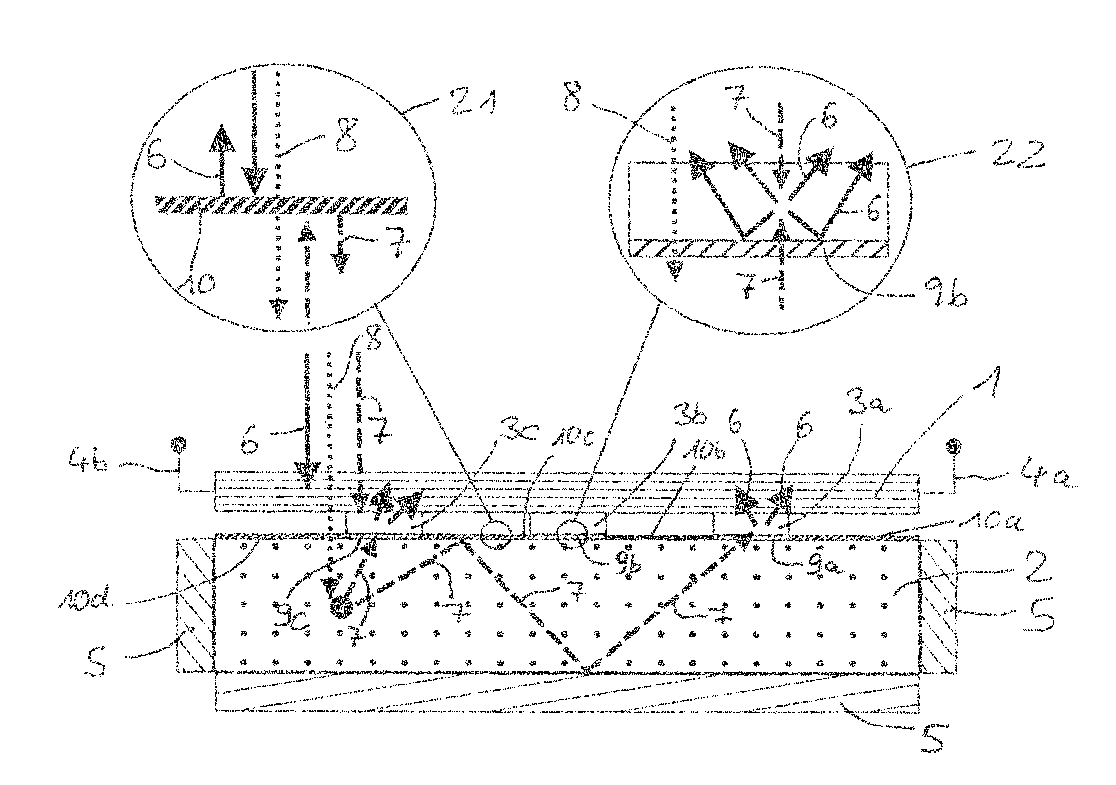
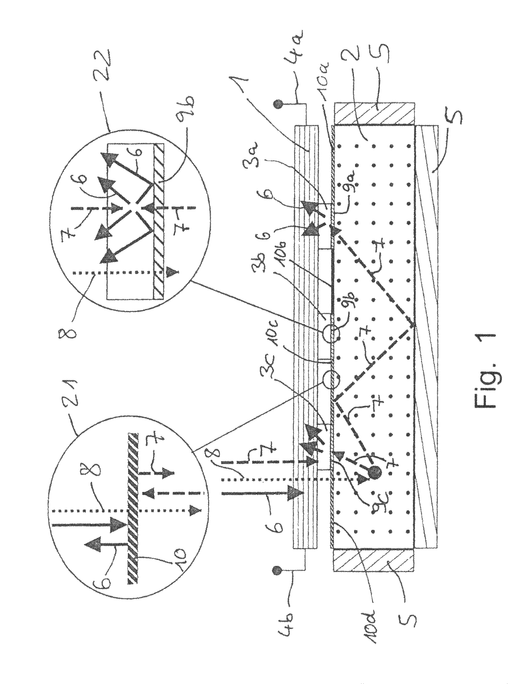
[0037]FIG. 1 shows a possible embodiment of the present invention. A cuboid luminescent element 2 is hereby provided on five sides with mirrors 5. A solar cell is disposed next to the sixth side of the luminescent element 2 which is not provided with mirrors 5 with a plane parallel to this side. Between the solar cell 1 and the side of the luminescent material 2 not provided with mirrors, upconverters 3a, 3b and 3c are disposed. These upconverters touch the solar cell 1 directly. Between the luminescent element 2 and the upconverters 3a, 3b and 3c, respectively one first selectively reflecting layer 9a, 9b and 9c is disposed.

[0038]Section 22 shows the permeability of the first selectively reflecting layer 9b. Radiation 6, the frequency of which is above the band gap frequency vBG of the solar cell 1, is reflected from the selectively reflecting layer 9b. Radiation 8, which is absorbed by the luminescent material, i.e. has a frequency between vLE1 and vLE2, is transmitted from the se...


PUM


Abstract

A solar element with increased efficiency and also a method for increasing the efficiency of a solar cell are provided. The solar cell comprises a luminescent element, an upconverter, and also at least one selectively reflecting structure.

Description

BACKGROUND OF THE INVENTION[0001]The present invention relates to a solar element with increased efficiency and also to a method for increasing the efficiency of a solar cell.[0002]More than 20% of the energy contained in the solar spectrum is lost during conversion of the incident radiation by means of silicon solar cells as a result of so-called sub-band gap losses. There are herewith described losses which are produced because the energy of a single photon does not suffice to produce a freely moveable electron. They occur when the energy of a photon falls below the so-called band gap energy. Losses of this type occur in all types of solar cells. Their level is dependent upon the band gap energy of the solar cell material which is used. The described losses can be reduced in that a plurality of photons with too low energy are converted with so-called upconverting materials into one photon with sufficient energy.[0003]The following problems hereby occur: firstly the absorption rang...

Claims


Application Information

Patent Timeline
IPC IPC(8): H01L31/00
CPCH01L31/055H01L31/0547Y02E10/52
Inventor GOLDSCHMIDT, JAN CHRISTOPHLOEPER, PHILIPPPETERS, MARIUS
Owner ALBERT LUDWIGS UNIV FREIBURG
Why Eureka
Try Eureka