Method for controlling a power bridge, and corresponding control device, power bridge and rotary electric machine system
Active Publication Date: 2015-04-23
VALEO EQUIP ELECTRIC MOTEUR
View PDF4 Cites 2 Cited by
Summary
Abstract
Description
Claims
Application Information
AI Technical Summary
This helps you quickly interpret patents by identifying the three key elements:
Problems solved by technology
Method used
Benefits of technology
Benefits of technology
The invention aims to minimize the loss of power in a power bridge's arms to allow for a larger amount of current at low frequencies. This is achieved by reducing the voltage in the common mode, which helps to reduce switching losses at higher frequencies.
Problems solved by technology
However, in the phases of starting of the rotary electrical machine, or with the rotor blocked, the electrical frequency is very low, or zero.
Method used
Image
Click on the blue label to locate the original text in one second.
Reading with bidirectional positioning of images and text.
Examples
example 1
[0054]A system 1, 2, 3, 4, 5 comprises a battery 2 with a voltage Ubat of 100 V, and a three-phase machine 1, the rotor of which is blocked.
[0060]The total losses in the upper MOSFET HS1 are therefore:
Pcond.+Pcomm.=(RC1+⅓)*Ron*Iph12, i.e. 0.93*Ron.
[0061]The losses in the lower MOSFET LS1 of the arm B1 are only the conduction losses, since the switching losses have already been withstood by the upper MOSFET
[0062]The to...
example 2
[0064]The strategy of decreasing the losses by limited the number of switching operations implies blocking the arm where the phase intensity is greatest, and in this case the arm B1.
[0065]For this purpose, the set duty cycle RC1 becomes an optimised duty cycle RCop1, such that RCop1=1.
[0066]The two other set duty cycles RC2 and RC3 are increased by RCop1−RC1 in order to maintain the same voltage differences between phases, by increasing the common mode voltage:
RCop1=1 RCop2=0.85 RCop3=0.85
Vop1=100 V Vop2=85 V Vop3=85 V
[0067]The optimised common mode voltage is Vop0=90 V.
[0068]The machine 1 still has the same phase voltages:
Vop1−Vop2=15 V Vop2−Vop3=0 V Vop3−Vop1=−15 V
[0069]In this case, the losses are only conduction losses, since the arm B1 no longer switches. The total losses are therefore:
Pcond.=RCop1*Ron*Iph12 i.e. Ron
[0070]The losses in the upper MOSFET HS1 derived form the known strategy of minimisation are therefore in fact 7% higher than those derived from PWM control withou...
PUM
Abstract
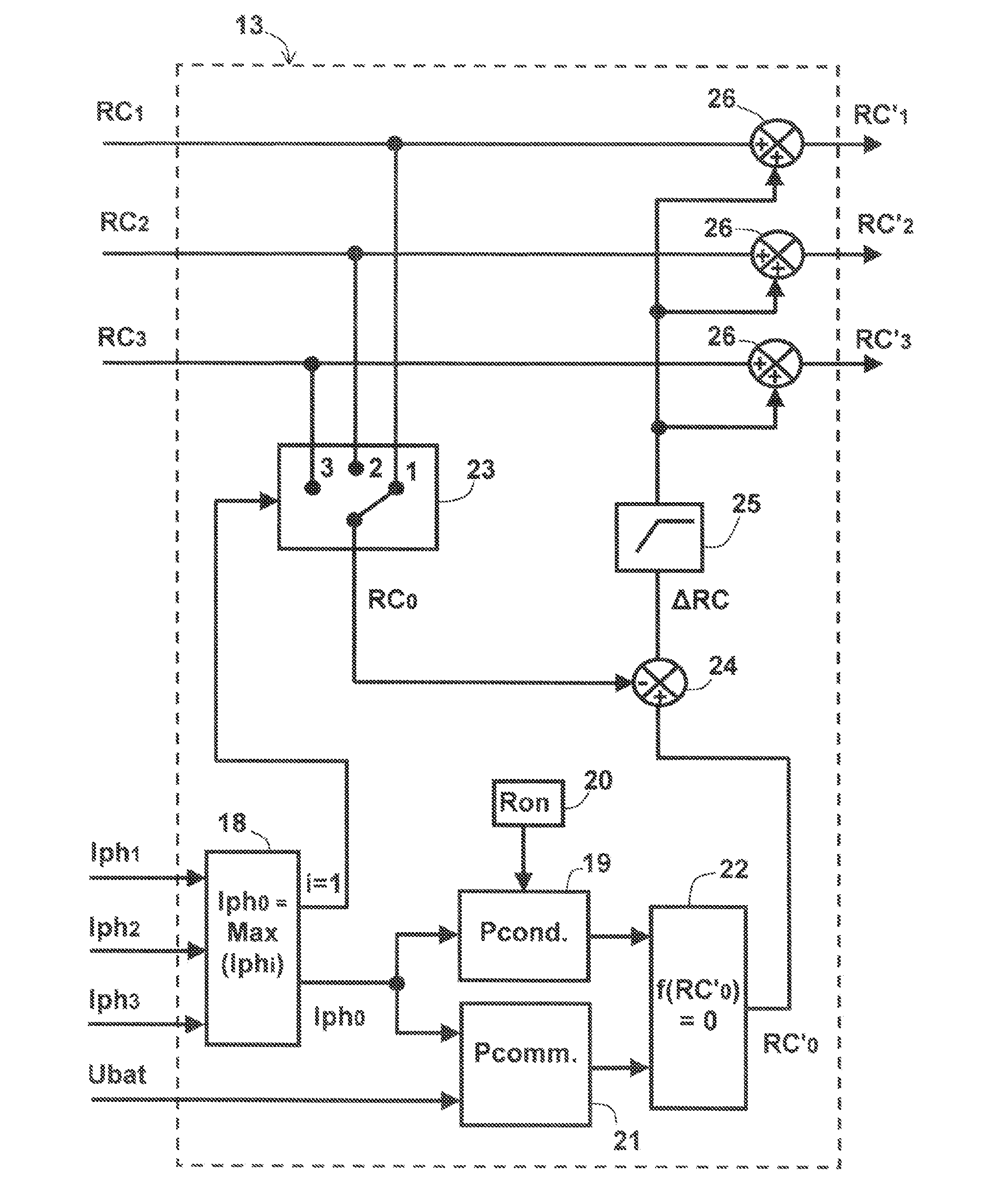
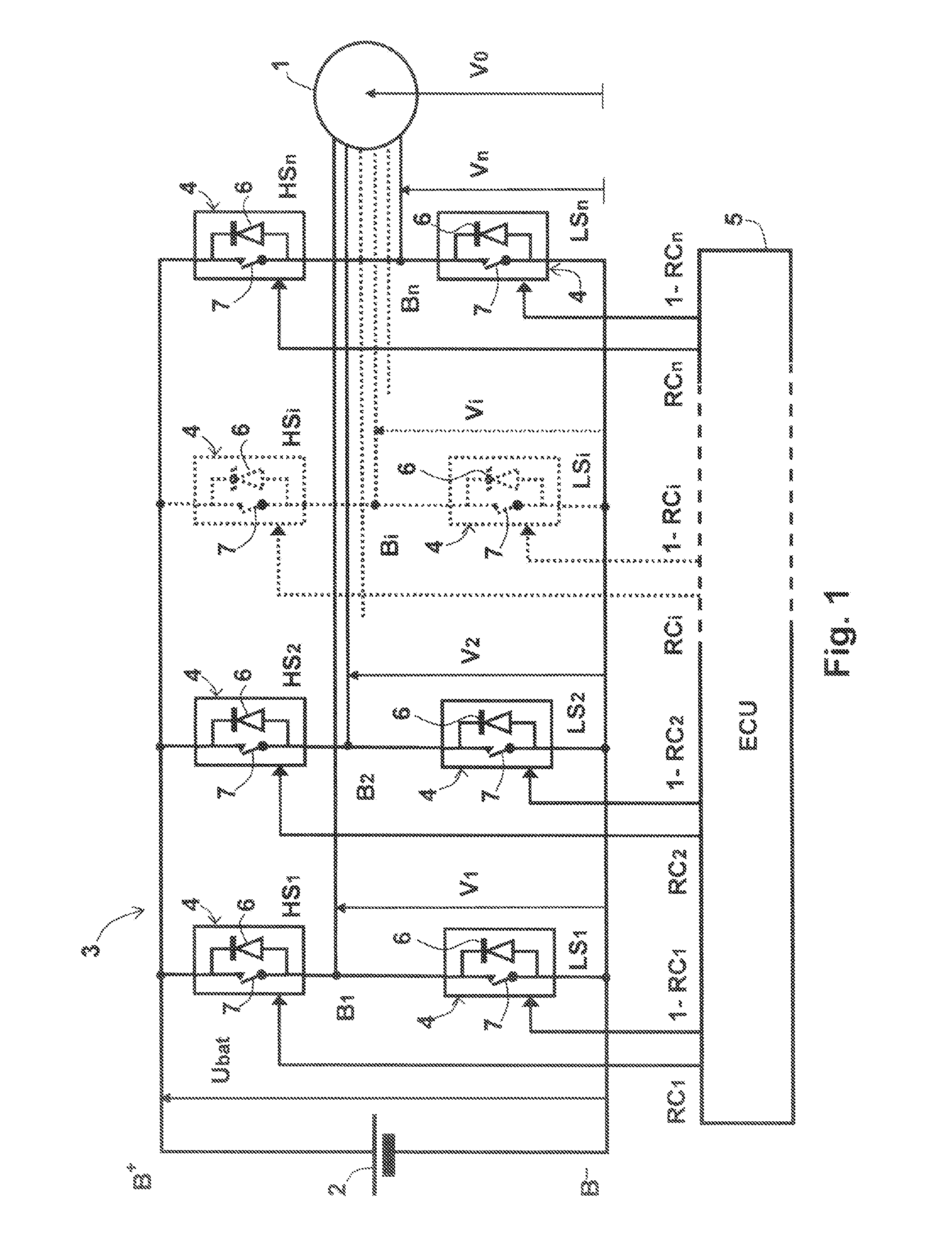
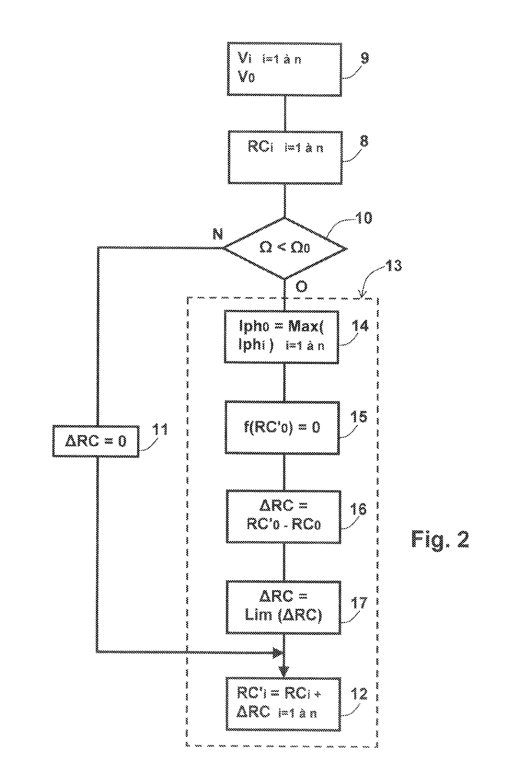
A method performed in a power bridge (3) comprising multiple arms (B1, B2, Bi, Bn). Each arm comprises upper and lower semiconductor switches arranged in series and connected in parallel to first and second terminals (B+, B−) of a common voltage source (2). The mid-point of the arm is connected to a phase of an electrical load (1). The aforementioned switches are controlled complementarily by pulses having a duty factor set value (RC1, RC2, RCi, RCn) determined as a function of a first phase voltage set value (V1, V2, Vi, Vn) in relation to a reference terminal of the electrical load (1) and of a common-mode voltage (V0) in relation to one of the first or second terminals, such as to control the switching losses of the switches. The common-mode voltage (V0) is determined such as to balance switching losses and conduction losses between the switches.
Description
TECHNICAL FIELD OF THE INVENTION[0001]The present invention relates to a method for controlling a power bridge which supplies a monophase or polyphase electric load, as well as to the corresponding control device.[0002]The invention also relates to an associated power bridge, as well as to its application to a rotary electrical machinesystem, in particular for a motor vehicle.TECHNOLOGICAL BACKGROUND OF THE INVENTION[0003]The rotary electrical machines which are produced in a large range of power levels and speeds are being used increasingly at present in the motor vehicle industry, as a result of considerations of protection of the environment.[0004]They have applications in vehicles of the all electric type, as well as in low CO2 emission vehicles of the so-called mild-hybrid and full-hybrid types.[0005]The mild-hybrid applications generally relate to electrical machines of approximately 8 to 10 kW, for example an electric motor which is fitted on the front surface of a thermal e...
Claims
Application Information
Patent Timeline
Application Date:The date an application was filed.
Publication Date:The date a patent or application was officially published.
First Publication Date:The earliest publication date of a patent with the same application number.
Issue Date:Publication date of the patent grant document.
PCT Entry Date:The Entry date of PCT National Phase.
Estimated Expiry Date:The statutory expiry date of a patent right according to the Patent Law, and it is the longest term of protection that the patent right can achieve without the termination of the patent right due to other reasons(Term extension factor has been taken into account ).
Invalid Date:Actual expiry date is based on effective date or publication date of legal transaction data of invalid patent.

