Signal transmission system

a transmission system and signal technology, applied in the direction of instruments, electric controllers, ignition automatic control, etc., can solve the problems of common mode interference, conventional data transmission systems suffer from insufficient signal quality, etc., and achieve the effect of suppressing the influence of interfering signals

Active Publication Date: 2013-08-13
III HLDG 6
View PDF10 Cites 38 Cited by
  • Summary
  • Abstract
  • Description
  • Claims
  • Application Information

AI Technical Summary

Benefits of technology

[0017]According to the invention, a system for calibrating a communication arrangement is provided, in which interference signals (or disturbing signals) are efficiently suppressed. In accordance with such a system, a sender is brought into a silent non-transmitting state. In this state, a transfer function of a receiver is adjusted in a manner to reduce an output signal of the receiver originating from interference signals in the environment as much as possible. Subsequently, the transmitter is adjusted in such a way that its transfer function is essentially inverse to the transfer function of the receiver. By doing so, common mode interferences are suppressed and a data transmission with an improved common mode rejection is obtained. Such a system allows for efficient suppression of an influence of interference signals on the signal transmission line even when multiple transmission paths are used (for instance in a differential data transmission system). This also holds for a scenario in which the interference signals couple into the different transmission paths in an unequal or different manner. It should be noted that the transmission channel can be wire based (for instance via a cable, for example in a similar manner as in a USB communication), or based on wireless communication according to a corresponding wireless data transmission protocol (for instance using a 13.56 MHz frequency of an RFID system, using a Bluetooth system, using infrared communication, etc.). Furthermore, it should be noted that signal processing and data communication calibration for suppressing interference signals and for improving the signal quality which is performed according to embodiments of the invention can be realized by a computer program, that is by software, or by using one or more special electronic optimization circuits, that is in hardware, or in hybrid form, that is by means of software components and hardware components.
[0022]It is advantageous if the method comprises the step of transmitting the signals from the transmitter to the receiver after having adjusted the receiver transfer function and after having set the transmitter transfer function. In other words, first, a calibration phase is performed, in which the receiver transfer function and the transmitter transfer functions are adjusted for an efficient suppression of an influence of interfering signals on the data transmission line. Subsequently, data communication is performed with proper data transmission quality.
[0023]It is furthermore advantageous if the method comprises the step of transmitting the signals via a multi channel (particularly multi-wire) communication from the transmitter to the receiver. For example, the signals are transmitted via two or more wires, for instance in a differential manner. In such a scenario it may happen that a interference signal couples into the different communication paths in a different manner. The interference signal suppression scheme according to an exemplary embodiment of the invention allows for a proper transmission quality even under such harsh circumstances.
[0025]Advantageously, the method also comprises the step of adjusting the receiver transfer function by adjusting a plurality of stages of the receiver. For example, the receiver has two input stages, and the transmitter has two output stages. Then, the transfer functions being indicative of the performance of the individual stages are adjusted individually, thereby improving accuracy of the adjustment. First, the sender is muted and then the receiver transfer functions is determined by adjusting the input stages of the receiver (e.g. in gain and phase) so that the output signal is a minimum. Finally, the sender transfer functions is set to the inverse receiver transfer functions, and the data transmission is started. By taking this measure, a compensation of different interference signals on a transmission line is possible, thereby particularly enabling improved data transmission via two or more wires.
[0035]According to another exemplary embodiment of the invention, the calibration and data transmission scheme as described hereinbefore is also used for suppressing distortions (like ripples) in a voltage generated by a voltage supply unit. By taking this measure, voltage drops or other distortions may be avoided. Particularly, a voltage smoothing effect is obtained. The system may be used in amplifiers in order to regulate a signal when signal distortions are measured. In a low-pass filter, a voltage may be smoothed by performing a frequency-dependent suppression of interference signals.

Problems solved by technology

In a data transmission system involving multiple transmission channels, over which signals are sent, problems with common mode interferences can occur.
However, conventional data transmission systems suffer from insufficient signal quality due to the influence of interference signals.

Method used


Image

  • Signal transmission system
  • Signal transmission system

Examples


Embodiment Construction

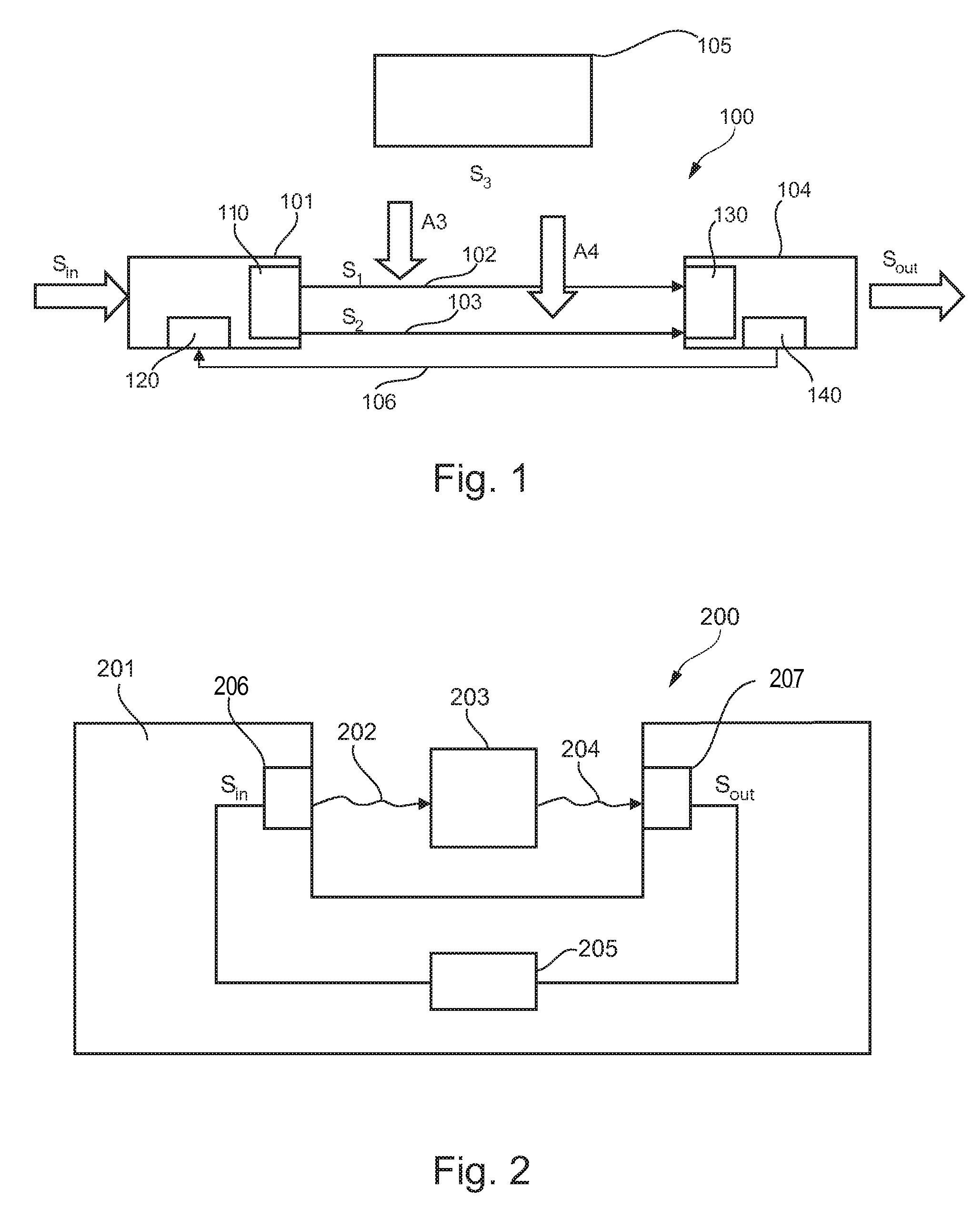
[0039]The illustration in the drawing is schematically. In different drawings, similar or identical elements are provided with the same reference signs.

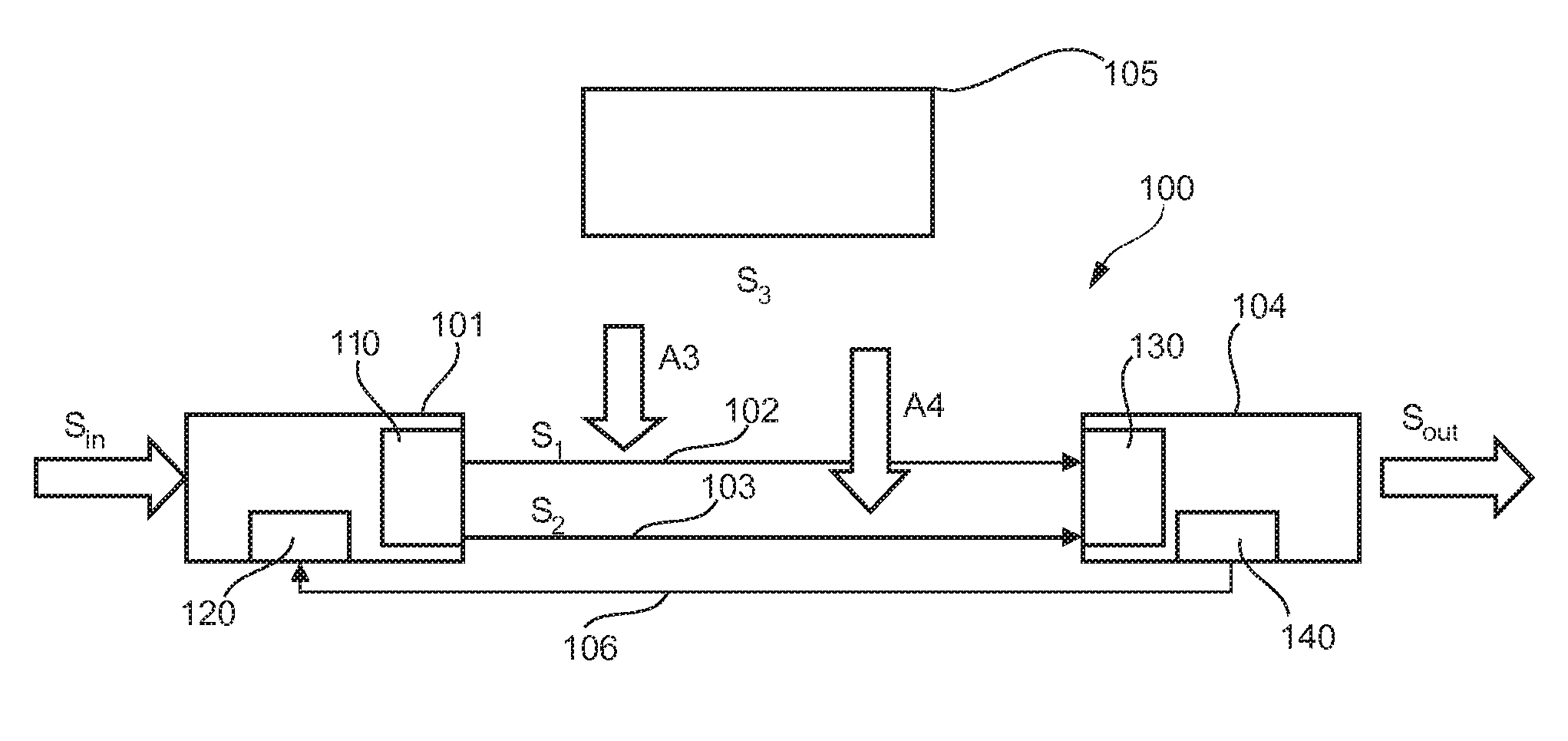
[0040]FIG. 1 shows a signal transmission system 100 according to an embodiment of the invention.

[0041]The signal transmission system 100 comprises a transmitter device 101 for transmitting a first signal s1 via a first data transmission channel 102 and for transmitting a second signal s2 via a second data transmission channel 103 to a receiver device 104. The signals s1 and s2 may be differential signals.

[0042]An input signal sin is supplied to an input of the transmitter 101. This input signal sin is processed within the transmitter 101 to generate the pair of differential signals s1 and s2 having opposite phase.

[0043]In this example, a source of interference 105 acts on the signals s1 and s2 during transmission over data transmission lines 102 and 103. The interference signal is denoted with s3. According to this embodiment, the in...


PUM


Abstract

A system is operated to transmit signals from a transmitter to a receiver. The transmitter is muted. A receiver transfer function for the receiver is adjusted so that an output signal of the receiver is minimized. A transmitter transfer function of the transmitter is set to be inverse to the adjusted receiver transfer function.

Description

FIELD OF THE INVENTION[0001]The invention relates to a method of operating a system for transmitting signals from a transmitter to a receiver.[0002]Moreover, the invention relates to a computer-readable medium.[0003]Furthermore, the invention relates to a program element.[0004]Furthermore, the invention relates to a transmitter.[0005]Furthermore, the invention relates to a receiver.[0006]Finally, the invention relates to a signal transmission system.BACKGROUND OF THE INVENTION[0007]Data transmission is important in many technical fields, including RFID (“radio frequency identification”) systems. In a data transmission system involving multiple transmission channels, over which signals are sent, problems with common mode interferences can occur. This term describes a signal disturbing phenomenon that can appear when a plurality of signal leads are influenced by a interference signal in the same manner.[0008]WO 2005 / 011139 discloses an electronic circuit to reduce noise in a digital s...

Claims


Application Information

Patent Timeline
Patent Type & Authority Patents(United States)
IPC IPC(8): H04B15/00
CPCG06K7/10237G06K19/0723H04L25/45
Inventor MICHELITSCH, MICHAEL
Owner III HLDG 6
Why Eureka
Try Eureka