Railway braking and throttle guidance user interface

Active Publication Date: 2013-08-13
SIEMENS MOBILITY INC
View PDF13 Cites 33 Cited by
  • Summary
  • Abstract
  • Description
  • Claims
  • Application Information

AI Technical Summary

Benefits of technology

[0014]Accordingly, an object of the invention is to create a train operator user interface that gives guidance to the operator when and how m

Problems solved by technology

Energy and scheduling time are wasted when an OBU forces a train to come to a full stop from steady state operating conditions, ascertain the events causing the stop, and restart the train back up to operating s

Method used


Image

  • Railway braking and throttle guidance user interface
  • Railway braking and throttle guidance user interface
  • Railway braking and throttle guidance user interface

Examples


Embodiment Construction

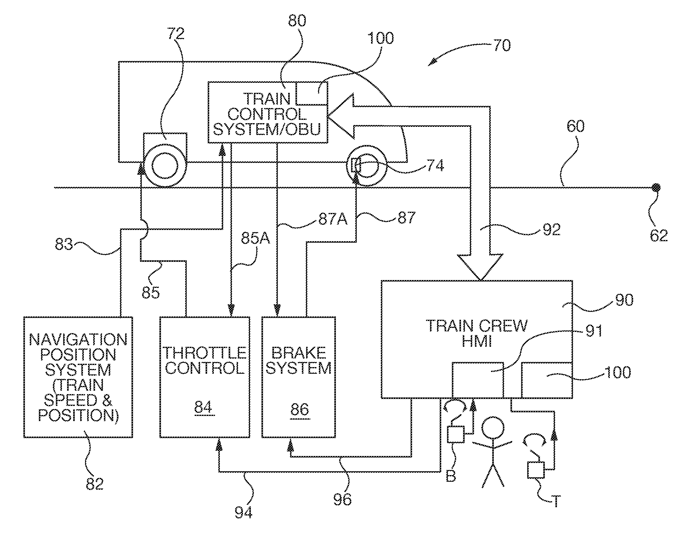
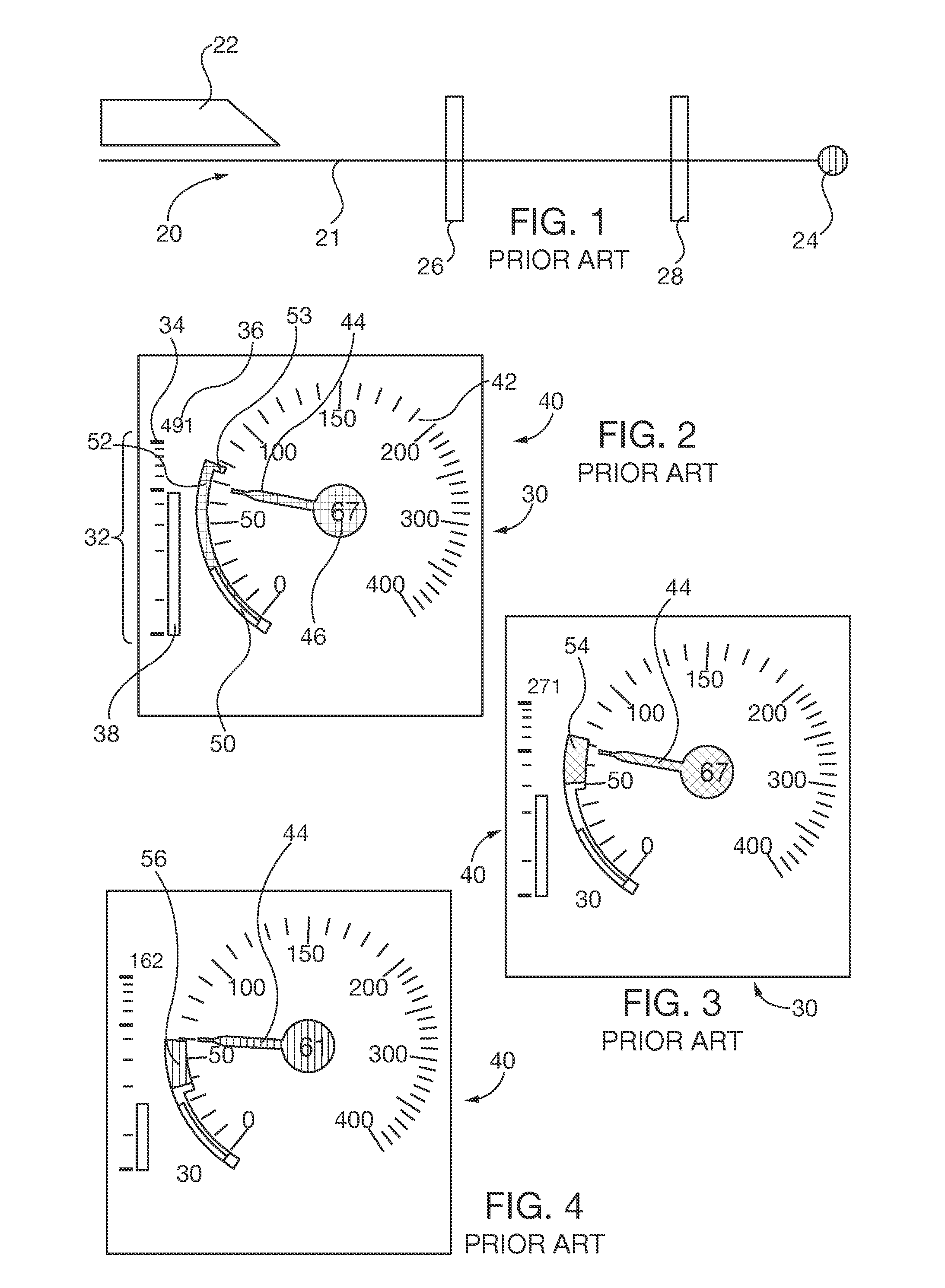
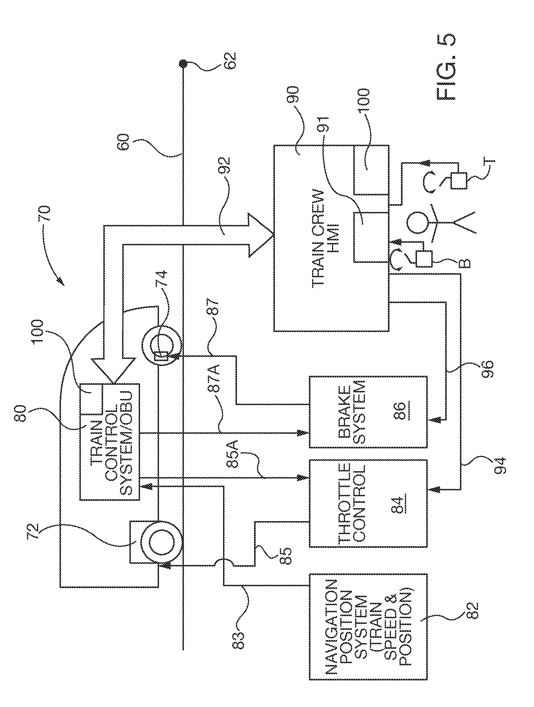
[0037]After considering the following description, those skilled in the art will clearly realize that the teachings of the present invention can be readily utilized in railway train user interfaces that assist train, operators to by suggesting optimal or desirable speed control throttle and / or brake application settings and intuitive feedback whether the operator is successfully conforming actual speed control settings to the suggested settings. The interface of the present invention alerts and helps the train operator intuitively recognize train distance from critical points along the railway track. The interface of the present invention also alerts the train operator whether train speed conforms with local speed restrictions and offers intuitively recognizable guidance on how to alter train speed with sufficient reaction time to avoid excessively rapid braking or OBU intervention that otherwise wastes fuel and disrupts travel schedules. The speedometer display of the present inven...


PUM


Abstract

A user interface includes a visual display with suggested speed control throttle and/or brake settings display portion, a speedometer display portion and a distance to target guide portion. The display provides intuitive feedback information helpful for train operator decisions on how and when to change train speed control throttle and/or brake settings. In some embodiments of the present invention the interface suggests brake and/or throttle settings for reducing train speed. The distance to target guide portion includes an analog target display that grows in size as the train approaches a target point speed change or stop position. The speedometer includes analog speed scale, speed indicator needle and a suggested target speed indicator display portions.

Description

BACKGROUND OF THE DISCLOSURE[0001]1. Field of the Invention[0002]The invention relates to controlling movement and speed of trains on railways, and more particularly to a user interface that assists train operators to optimize throttle and brake application of train speed controls. As used herein, the term “train” is a locomotive alone, one or more locomotives with cars, or an integrated locomotive / car vehicle, (e.g., light rail or subway).[0003]2. Description of the Prior Art[0004]Rail lines establish maximum local operating speeds along the track right of way, dictated among other things by track conditions, train line congestion and distances ahead of trains that are needed for braking and acceleration to different speeds. Railway operators also establish points of interest along the railway tracks that suggest minimal or optimal speeds for local track conditions, efficient energy usage and travel scheduling. Other or units exist along the railway tracks that mandate maximum spee...

Claims


Application Information

Patent Timeline
IPC IPC(8): G05D1/00G05D3/00G06F17/00G06F7/00B60T13/66B61L3/00
CPCB61L15/009B61L3/006B61L25/021B61L25/025B61L2205/04B60L2200/26B61L3/008B60T13/665Y02T10/7258B60T7/18B60T7/22B60T17/228Y02T10/72
Inventor ISAILOVSKI, ALEKSANDERKRIETEMEYER, JAMES
Owner SIEMENS MOBILITY INC
Why Eureka
Try Eureka