Gas burner for cooking appliances

a technology for cooking appliances and burners, which is applied in the direction of gaseous heating fuel, combustion types, domestic stoves or ranges, etc., can solve the problems of extinguishing the simmering flames, and achieve the effects of convenient installation, reliable operation and particularly simple access to injectors

Active Publication Date: 2013-08-20
E G O ELEKTRO GERAETEBAU GMBH
View PDF12 Cites 10 Cited by
  • Summary
  • Abstract
  • Description
  • Claims
  • Application Information

AI Technical Summary

Benefits of technology

[0007]Another object of the invention is to provide a gas burner in which the simmering flame ring can be fed with a minimum gas flow, that is far less than that at which in traditional burners can function satisfactorily. The instant gas burner employs a cover, with an outwardly extending edge that shields the passages feeding the ring of simmering flames from ambient conditions or disturbances.
[0008]Another object of the invention is to provide a gas burner with a simmering flame ring in which injector access is particularly simple, to enable replacement if the appliance is to be adapted for different gas types.
[0009]Another object of the invention is to provide a gas burner with a minimum number of parts that leads to economy of manufacture, reliable operation, and ease of installation both in cooking hobs and in gas cookers.
[0010]Another object of the invention is to provide a gas burner of extremely small height attributable to superimposed chambers, and hence capable of installation in cooking hobs of minimum thickness.

Problems solved by technology

However the simmering flame ring is disposed on the circumferential wall of the burner and is sensitive to those air movements which inevitably occur on the cooking hob.
Moreover, the primary air feeding the simmering flame ring originates from below the cooking hob with the result that this ring, already fed with a minimum gas flow and sensitive to air movements on the cooking hob, is also sensitive to the streaming effect, i.e. the pressure reduction to which the primary air flow is exposed following opening of a door positioned below the cooking hob, which can result in extinguishing of the simmering flames.

Method used


Image

  • Gas burner for cooking appliances
  • Gas burner for cooking appliances
  • Gas burner for cooking appliances

Examples


Embodiment Construction

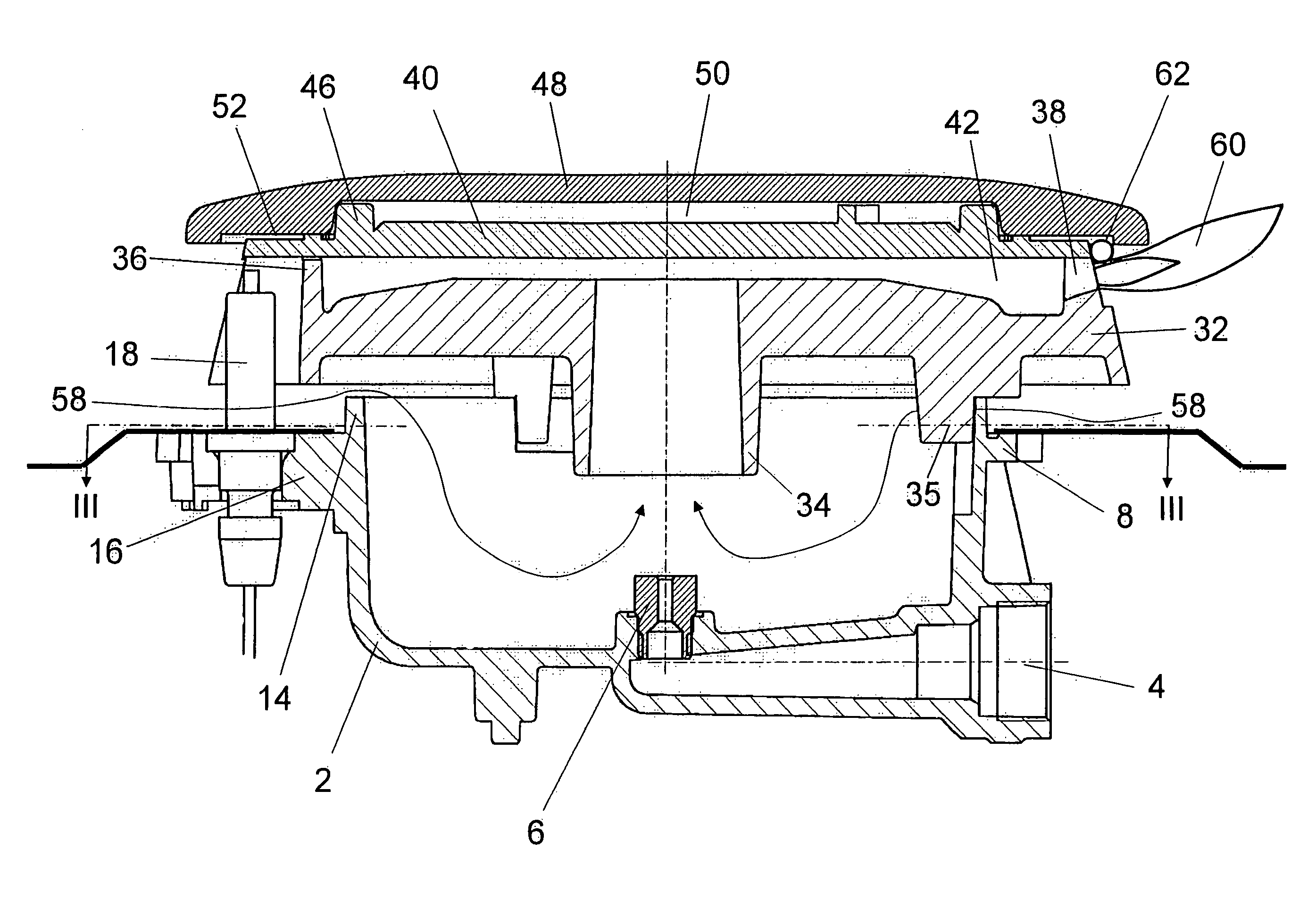
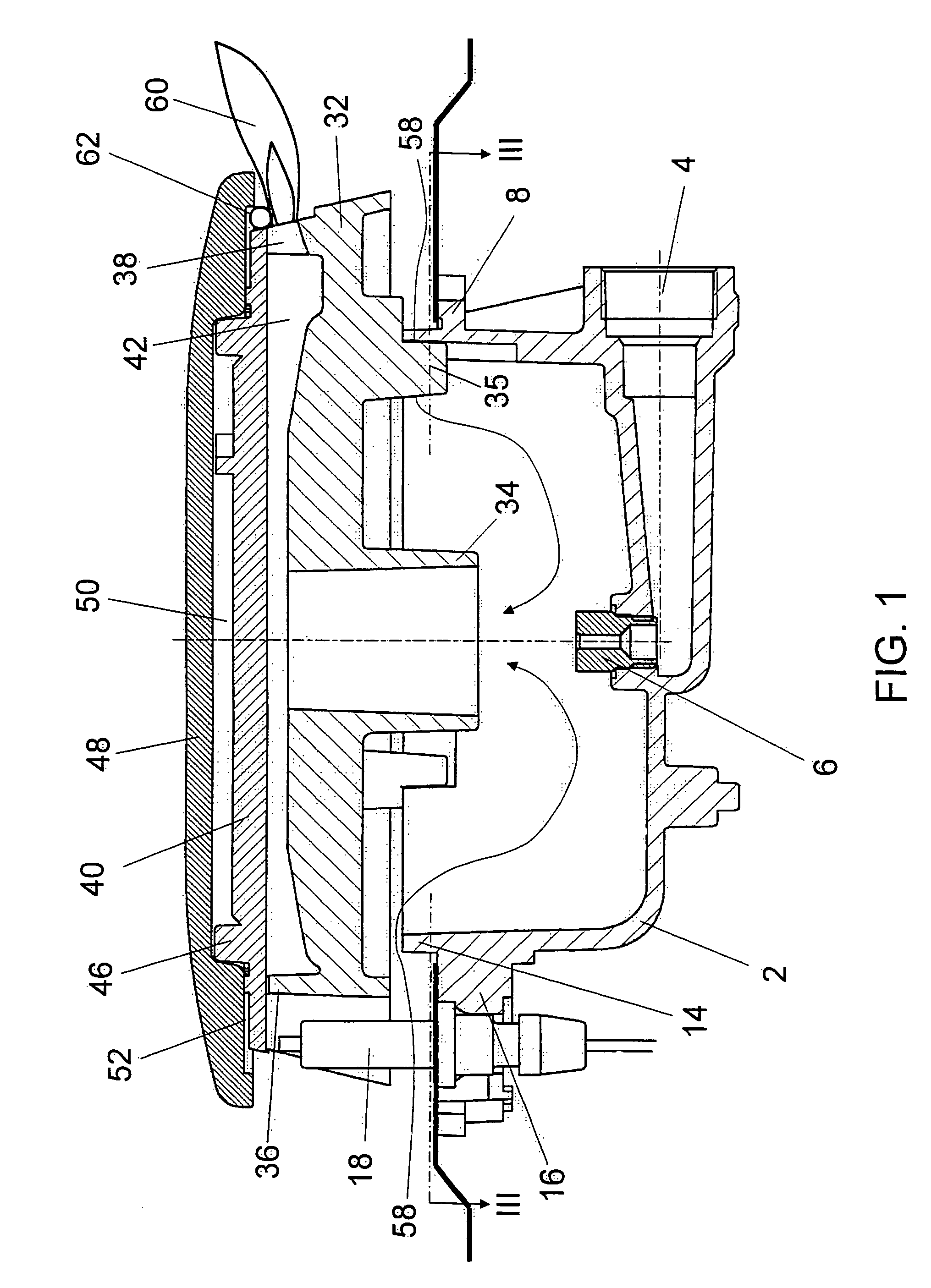
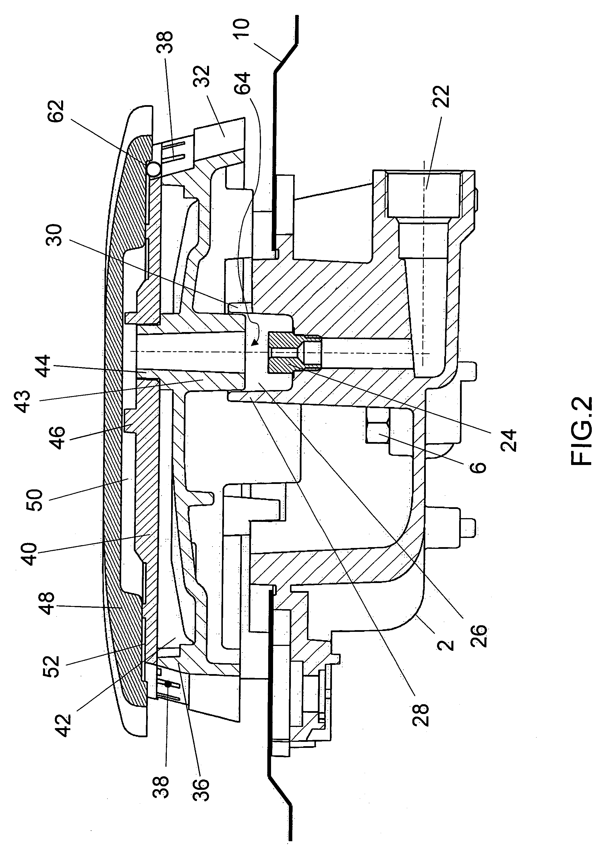
[0019]As can be seen from the figures, the burner of the invention comprises, in the embodiment shown in FIGS. 1-5, a cup-shaped support 2 closed at its base and provided with a first inlet 4 for the gas feeding a first injector 6, which is positioned in the center of said base and is intended to feed the main flame ring.

[0020]The cup-shaped support 2 is provided with a flange 8, by which it rests on the lower surface of the cooking hob 10, formed of sheet metal, at an aperture provided therein. Screws 12 fix the support to hob 10.

[0021]The cup-shaped support 2 extends beyond the hob 10 as a raised edge 14 and is also provided, below said hob, with a radial appendix 16 supporting an ignition spark plug 18 and a thermocouple 20.

[0022]The cup-shaped support 2 is also provided with a second inlet 22 for the gas which feeds a second injector 24 positioned eccentrically to the first injector 6 and is intended to feed the simmering flame ring.

[0023]Because of the minimum gas flow for the ...


PUM


Abstract

A gas burner for cooking appliances employing a ring of main flames for cooking, and a ring of simmering flames for heating. A first chamber contains the gas and primary air mixture for feeding the ring of main flames through a circumferential wall with a plurality of radial apertures. The chamber contains the gas and primary air mixture for feeding the ring of simmering flames through radial passages. The chambers are superposed, and a separator plate is interposed between the chambers. A cover rests on the separator plate and the radial apertures are defined therebetween. The cover extends beyond the passage and shields same from ambient conditions.

Description

[0001]The present invention relates to a gas burner for cooking appliances.[0002]Gas burners with one or more flame rings are known, in particular gas burners with a ring of main flames positioned at a certain level of the burner and a ring of simmering flames positioned at a different level.[0003]The main flame ring is used to deliver the power required for high temperature cooking, whereas the simmering flame ring is used to provide minimum power delivery, to be used for low temperature cooking; the lower the temperature provided by the simmering flame ring, the better the burner performance.BACKGROUND OF THE INVENTION[0004]U.S. Pat. No. 6,263,868 granted Jul. 24, 2001, to J. Koch et al, describes a gas burner with two flame rings positioned at different heights, namely a main flame ring positioned at a higher level and a simmering flame ring positioned at a lower level. However the simmering flame ring is disposed on the circumferential wall of the burner and is sensitive to thos...

Claims


Application Information

Patent Timeline
Patent Type & Authority Patents(United States)
IPC IPC(8): F24C3/08
CPCF23D14/06F23D14/26F23D14/74F23D2900/14063F23D2900/14062
Inventor PAESANI, CARLO
Owner E G O ELEKTRO GERAETEBAU GMBH
Why Eureka
Try Eureka