
Oxygen supply device and method for supplying a passenger cabin of an aircraft with oxygen

a technology for aircraft and oxygen supply, applied in the direction of oxygen/ozone/oxide/hydroxide, aircraft crew accommodation, energy-saving board measures, etc., can solve the problems of reducing the oxygen generation capacity of the aircraft, requiring electronic measurement and control devices, and limiting the electropneumatic flow. , to achieve the effect of reducing the power consumption of the aircra

Active Publication Date: 2021-08-24
AIRBUS OPERATIONS GMBH
View PDF23 Cites 0 Cited by
  • Summary
  • Abstract
  • Description
  • Claims
  • Application Information

AI Technical Summary

Benefits of technology

The present invention reduces power consumption in aircraft by combining two techniques for supplying oxygen: chemical and pressurized gas. The chemical oxygen is generated for a short time using a small chemical generator, and the energy generated is stored in an energy store. The stored energy is then used to operate the oxygen flow regulation from a pressurized tank, eliminating the need for an external power source. This results in a significant reduction of power consumption for supplying oxygen to the passenger cabin of an aircraft. The control unit ensures a constant flow of oxygen to the consumer unit by minimizing the flow from the reaction tank and / or the pressurized tank. This allows for compliance with statutory regulations and ensures a smooth operation of the aircraft's oxygen supply system.

Problems solved by technology

However, because of the weight, this type of oxygen generation is less suitable for longer supply times of more than 30 minutes.
This requires electronic measurement and control devices and an electropneumatic flow limitation.

Method used


Image

  • Oxygen supply device and method for supplying a passenger cabin of an aircraft with oxygen
  • Oxygen supply device and method for supplying a passenger cabin of an aircraft with oxygen
  • Oxygen supply device and method for supplying a passenger cabin of an aircraft with oxygen

Examples


Embodiment Construction

[0040]The representations in the figures are schematic and not to scale.

[0041]If the same reference signs are used in various figures in the following description of the figures, these reference signs denote identical or similar elements. However, identical or similar elements may also be denoted by different reference signs.

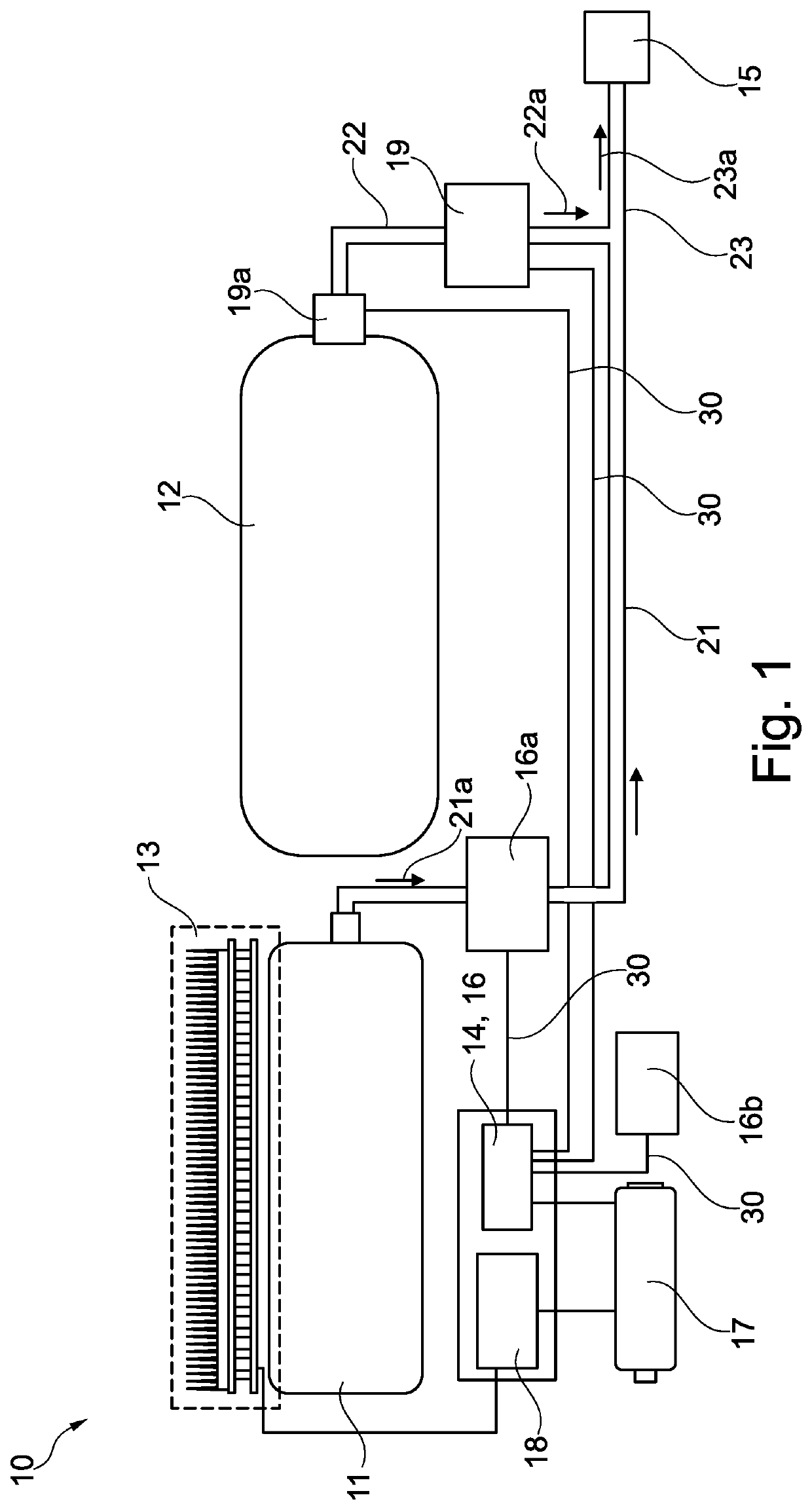
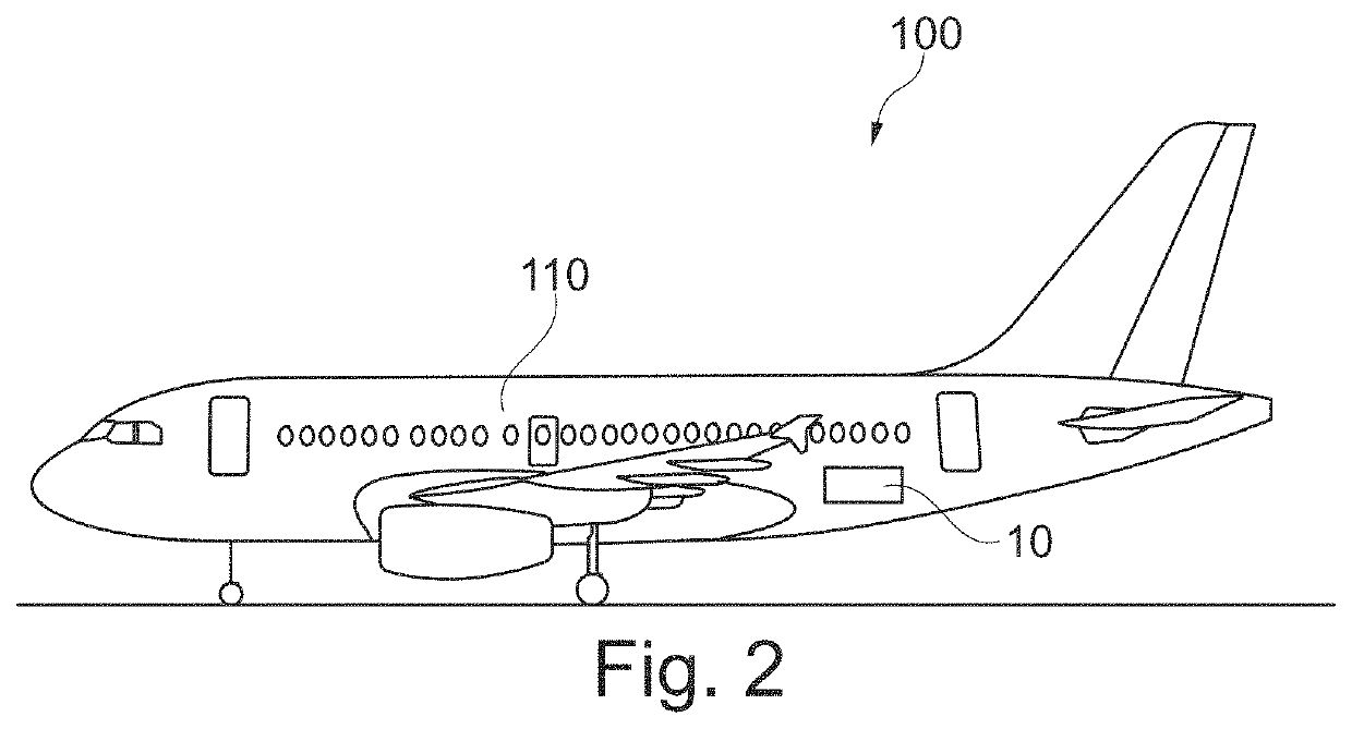
[0042]FIG. 1 shows a circuit diagram of an oxygen supply device 10. The oxygen supply device 10 may be part of an aircraft, in particular part of a passenger aircraft. The oxygen supply device 10 has a reaction tank 11 for chemical oxygen generation and a pressurized tank 12 filled with oxygen. The oxygen supply device 10 also has an energy converter 13 for converting thermal energy into electrical energy, in particular into electrical power. A voltage transformer 18 of the oxygen supply device 10 is designed to set a certain voltage on the basis of the electrical power generated by the energy converter 13. The electrical energy provided by the voltage transform...


PUM

PropertyMeasurementUnit
constant voltageaaaaaaaaaa
thermal energyaaaaaaaaaa
electrical energyaaaaaaaaaa

Abstract

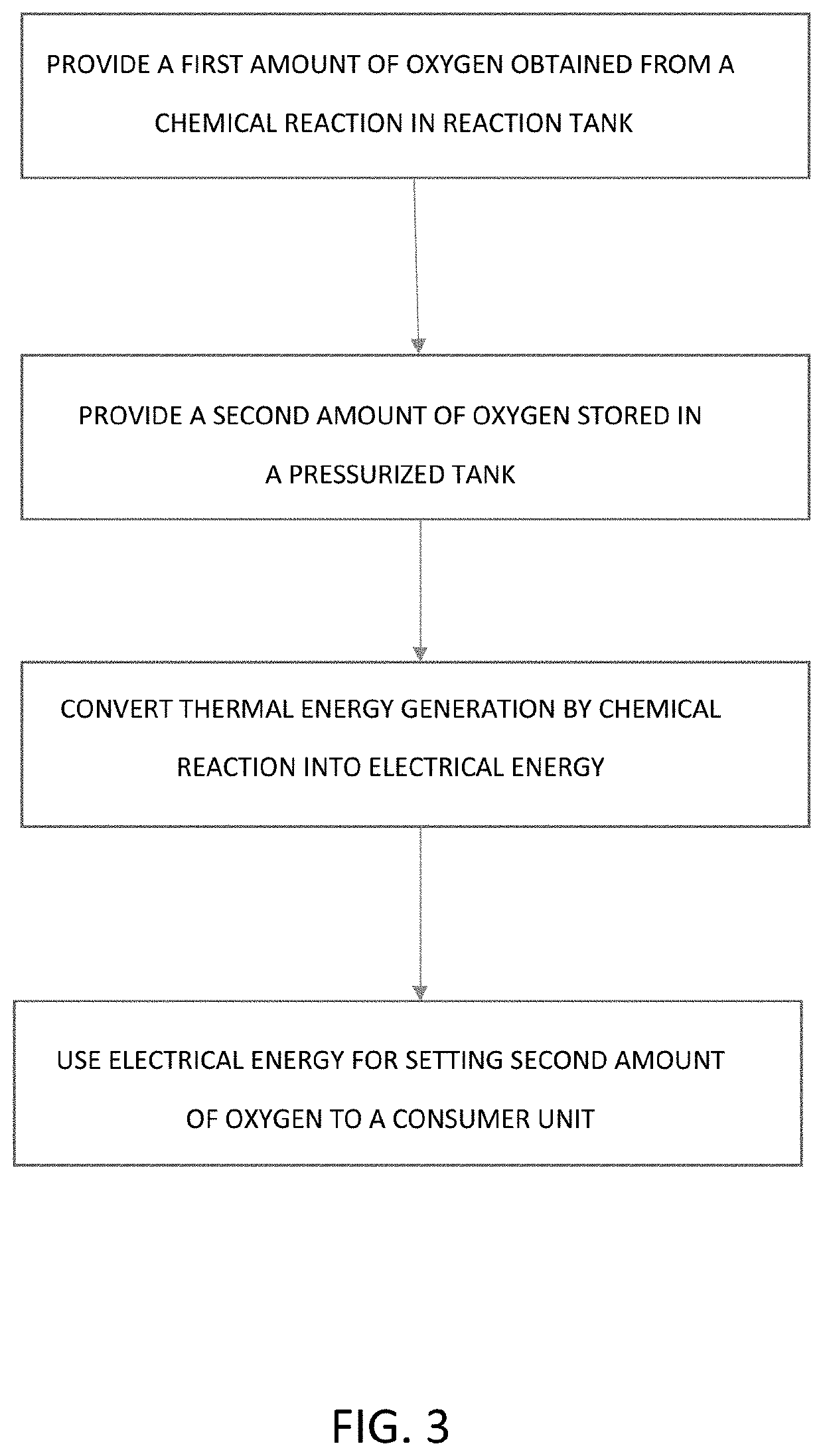
An oxygen supply device for an aircraft has a reaction tank for chemical oxygen generation and a pressurized tank filled with oxygen. The oxygen supply device also has an energy converter for converting thermal energy into electrical energy and also a control unit for setting a first amount of oxygen, provided by the reaction tank to a consumer unit, and a second amount of oxygen, provided by the pressurized tank to the consumer unit. The energy converter is designed to convert a thermal energy, generated by the chemical oxygen generation in the reaction tank, into electrical energy and to provide the electrical energy. The control unit is designed to set the second amount of oxygen, provided by the pressurized tank to the consumer unit, by using the electrical energy provided by the energy converter. The invention also relates to a method for supplying a passenger cabin of an aircraft with oxygen.

Description

FIELD OF THE INVENTION[0001]The present invention relates to supplying oxygen for aircraft and spacecraft systems. In particular, the invention relates to an oxygen supply device for an aircraft and to a method for supplying a passenger cabin of an aircraft with oxygen.BACKGROUND OF THE INVENTION[0002]Depending on the operating state of the aircraft, various possibilities come into consideration for supplying a passenger cabin of an aircraft with oxygen. The primary source for supplying air to the passenger cabin of an aircraft is generally the engines of the aircraft. However, other oxygen supply systems also come into consideration, such as for example the supply provided by compressed air from oxygen tanks or by chemically generated oxygen. A chemical oxygen supply uses a chemical reaction, which generates heat and oxygen without electrical energy being required for this. However, because of the weight, this type of oxygen generation is less suitable for longer supply times of mo...

Claims


Application Information

Patent Timeline
Patent Type & Authority Patents(United States)
IPC IPC(8): B64D13/06B01J7/00C01B13/02
CPCB64D13/06B01J7/00C01B13/02C01B13/0218B64D2013/064B64D2013/0648B64D2013/0677B64D2013/0681B64D13/00B64D11/00A62B7/14Y02T50/50Y02T50/40
Inventor LEUENBERGER, FRANKNEUMANN, CARSTEN
Owner AIRBUS OPERATIONS GMBH
Learn More