Piston setting device and method

a technology of a setting device and a piston, which is applied in the direction of liquid handling, instruments, packaged goods, etc., can solve the problems of affecting the performance of the discharged material, the failure of ventilation devices to meet the requirements of tight manufacturing tolerances, and the piston to til

Inactive Publication Date: 2013-08-20
SULZER MIXPAC AG
View PDF8 Cites 2 Cited by
  • Summary
  • Abstract
  • Description
  • Claims
  • Application Information

AI Technical Summary

Benefits of technology

[0013]The pressure differential between the cartridge chamber and the drive side of the piston is thereby increased. The drive side of the piston is the side of the piston opposite the filling mass, thus the side of the piston to which the piston setting device is attached to. As a consequence of the higher pressure differential, the air leaves the cartridge chamber more rapidly. Therefore the piston setting device can be operated at higher speed, which in turn allows for the displacement speed of the piston to be increased.
[0025]According to a preferred embodiment, the first end of the conduit has an inlet opening arranged adjacent said plunger. Alternatively the first end of the conduit may comprise a plurality of inlet openings. A plurality of inlet openings is in particular advantageous to increase the flow rate of the air. The inlet openings are preferably arranged circumferentially around the plunger, so that the flow path of the air is substantially the same regardless of the location of the passage at the engagement connection of the first piston part with the second piston part.

Problems solved by technology

It is desirable not to trap air in the cartridge chamber during this setting operation due to the fact that air may be harmful for the component stored in the cartridge chamber and due to the fact that air as a compressible gas may cause the piston to tilt when moved for discharging the filling mass from the cartridge.
Additionally, the presence of a compressible gas will cause a pressure variation inside the chamber during dispensing which creates undesirable variations in flow and may result in poor performance of discharged material.
However, volatile components of the filling mass can penetrate the micropore filter, which may lead to leakage.
However, this ventilation device can only be manufactured with tight manufacturing tolerances.
Another disadvantage can be seen in that parts of the filling mass can advance up to the valves, which are then contaminated, so that their sealing function is adversely affected.
Additionally, many materials packaged in cartridges are very viscous and form irregular surfaces rendering current piston setting techniques ineffective.

Method used


Image

  • Piston setting device and method
  • Piston setting device and method
  • Piston setting device and method

Examples


first embodiment

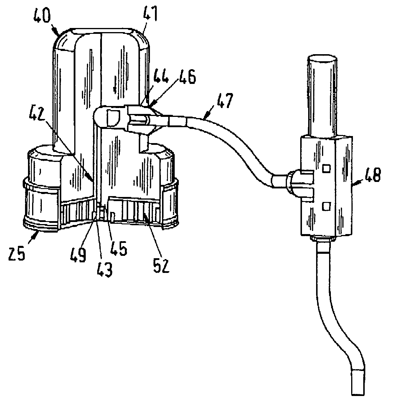
[0055]FIG. 3a shows a piston 25 according to FIG. 1 and a piston setting device 40 attached to said piston 25 according to the invention.

[0056]The piston setting device 40 for a cartridge comprises a housing 41, a conduit 42 arranged in said housing, said conduit 42 having a first end 43 and a second end 44, said first end 43 comprising a plunger 45, said plunger 45 being connectable to a valve plug 7 of a venting valve 21 of the piston for displacing said valve plug 7 to an open position for allowing air to flow through the conduit 42 and the second end 44 comprising an attachment element 46 connectable to a vacuum source 48. The attachment element 46 can be plugged into the conduit 42. This allows for an easy assembly and disassembly of the attachment element 46. The attachment element 46 can be a conventional hose adapter. Alternatively a thread can be provided in the conduit 42 at the second end 44 thereof for receiving the attachment element 46. Such a thread is shown in FIG. 4...

second embodiment

[0060]FIG. 3b shows a piston 25 according to FIG. 1 and a piston setting device 40 attached to said piston 25 according to the invention. Parts which have the same function as in FIG. 3a carry the same reference numerals and it is referred to the description of FIG. 3a for these parts. The piston setting device according to FIG. 3b comprises an interior plunger 150 which has a longitudinal axis 153. As shown in FIG. 3c, the piston has a venting valve 21 which is arranged in the central area of the piston, that means the axis of symmetry 154 of the venting valve 21 corresponds to the axis of symmetry 153 of the piston. However the location of the interior plunger 150 essentially depends on the location of the venting valve 21 on the piston. Preferably the axis of symmetry 154 of the venting valve 21 essentially corresponds to the longitudinal axis 153 of the interior plunger 150.

[0061]The interior plunger 150 is according to the embodiment of FIG. 3b movable with respect to the housi...


PUM

PropertyMeasurementUnit
thicknessaaaaaaaaaa
thicknessaaaaaaaaaa
filling massaaaaaaaaaa

Abstract

The system for filling a cartridge employs a piston setting device that has a plunger for moving the venting valve of the piston to an open position and a conduit for venting the air from the opened valve under the influence of a vacuum source connected to the conduit via an attachment device.

Description

FIELD OF THE INVENTION[0001]The invention is broadly concerned with dispensing cartridges for fluid filling masses, in particular with multicomponent cartridges which are used for dispensing two or more components contemporaneously. In a multicomponent cartridge, each of the components is stored into its own storage chamber prior to dispensing. The storage chamber for each one of the components is separate from the storage chamber for any of the other components, such that the components may not mix during the storage period. The innovation pertains in particular to a cartridge comprising a piston setting device and a piston setting device for a cartridge as well as a method for operating a piston setting device to set a piston in said cartridge.BACKGROUND OF THE INVENTION[0002]When filling a cartridge chamber of a cartridge with a filling mass, it is common practice to close the cartridge chamber by inserting a piston into the cartridge chamber containing the filling mass. That mea...

Claims


Application Information

Patent Timeline
Patent Type & Authority Patents(United States)
IPC IPC(8): B65B1/04B65D88/54B67D7/60G01F11/00
CPCB05C17/00579B05C17/00553B05C17/005B65B3/12B65D81/32
Inventor TURNER, HAYDEN
Owner SULZER MIXPAC AG
Why Eureka
Try Eureka