System and method for distributing fuel from a hydrant pit valve at an airport

Active Publication Date: 2013-08-20
GENERAL TRANSERVICE
View PDF14 Cites 15 Cited by
  • Summary
  • Abstract
  • Description
  • Claims
  • Application Information

AI Technical Summary

Problems solved by technology

For at least that reason, most fuel trucks are not designed to transfer fuel from a hydrant pit valve to an aircraft.

Method used


Image

  • System and method for distributing fuel from a hydrant pit valve at an airport
  • System and method for distributing fuel from a hydrant pit valve at an airport
  • System and method for distributing fuel from a hydrant pit valve at an airport

Examples


Embodiment Construction

[0015]In the figures, identical item numbers in different figures refer to identical components.

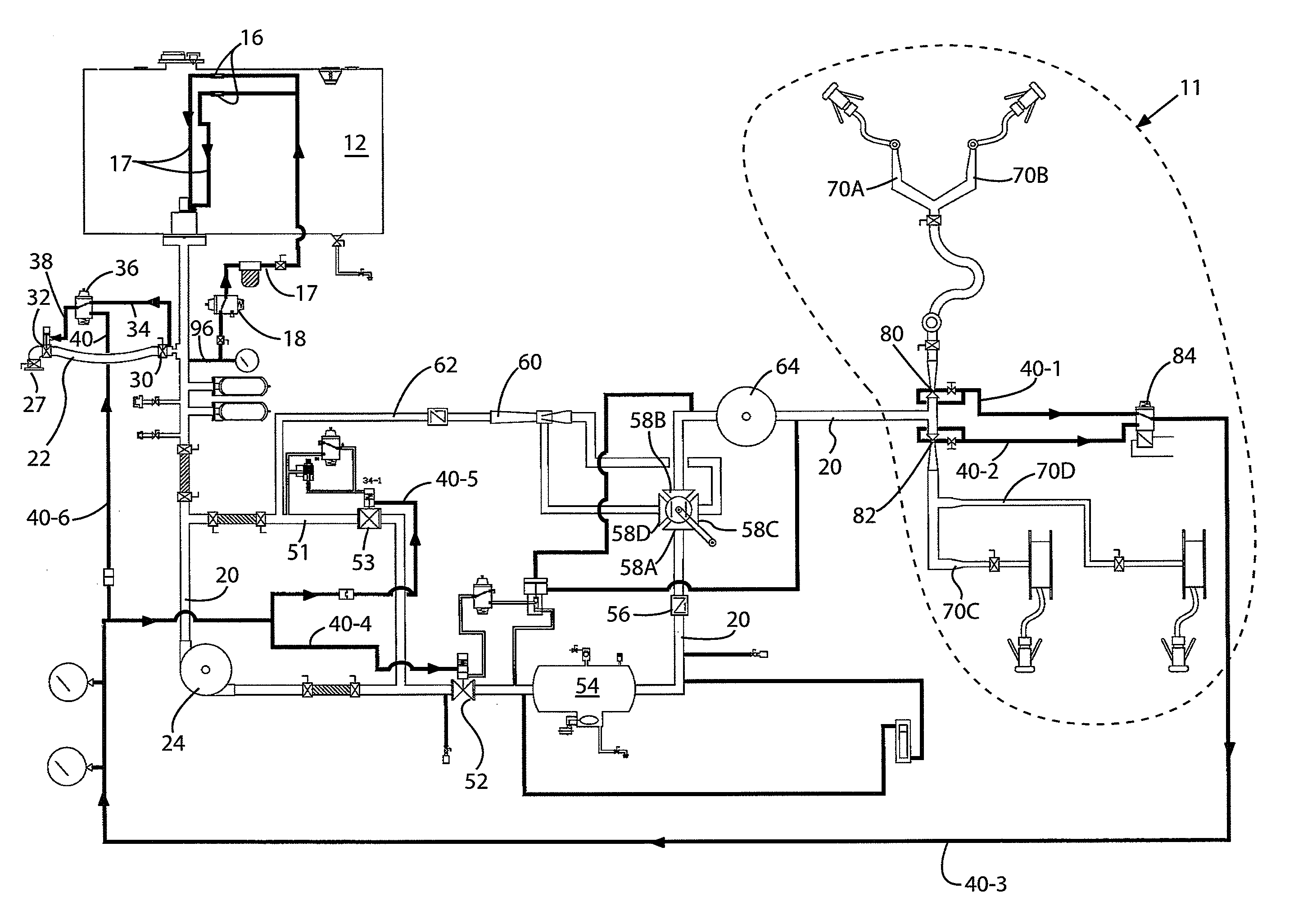
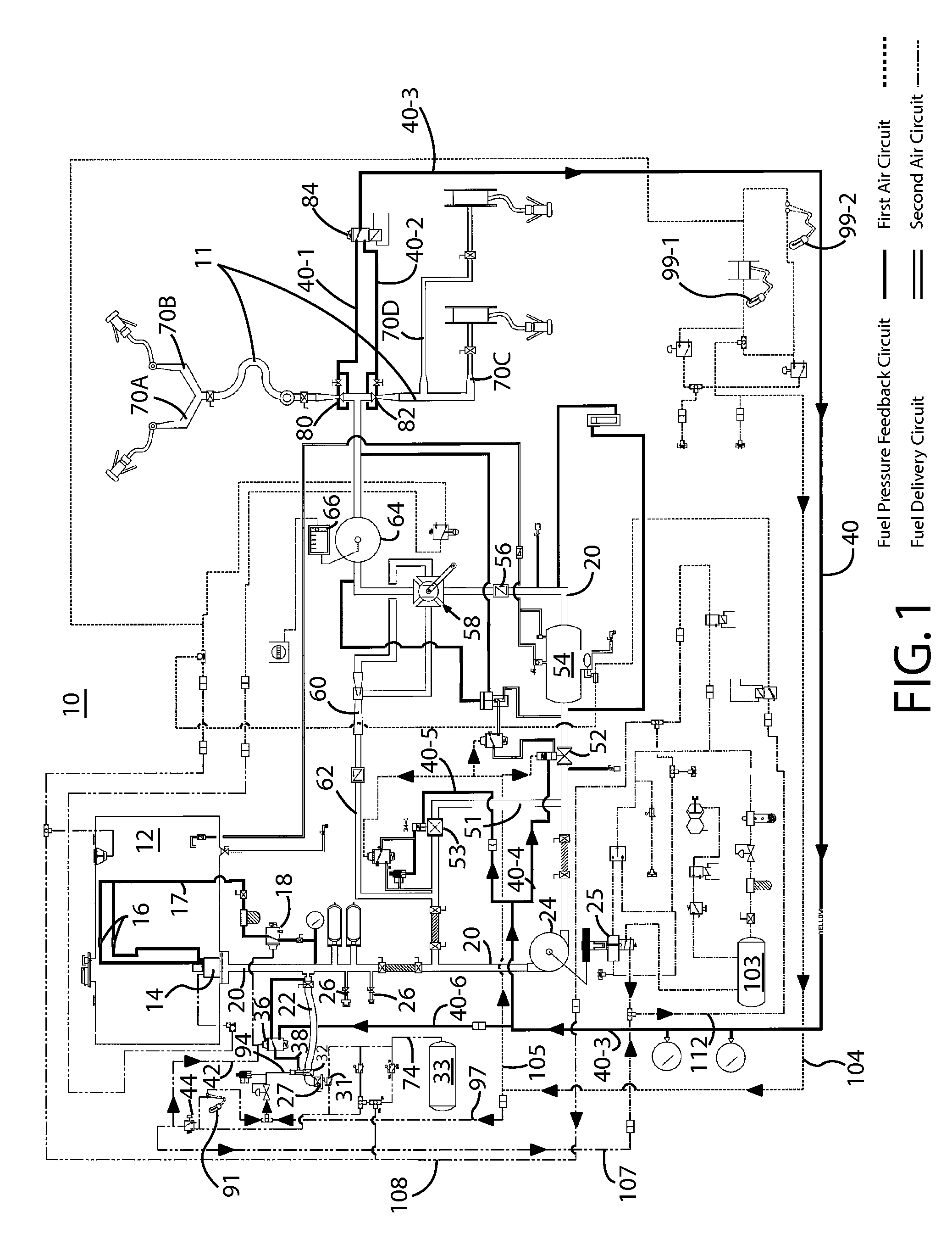
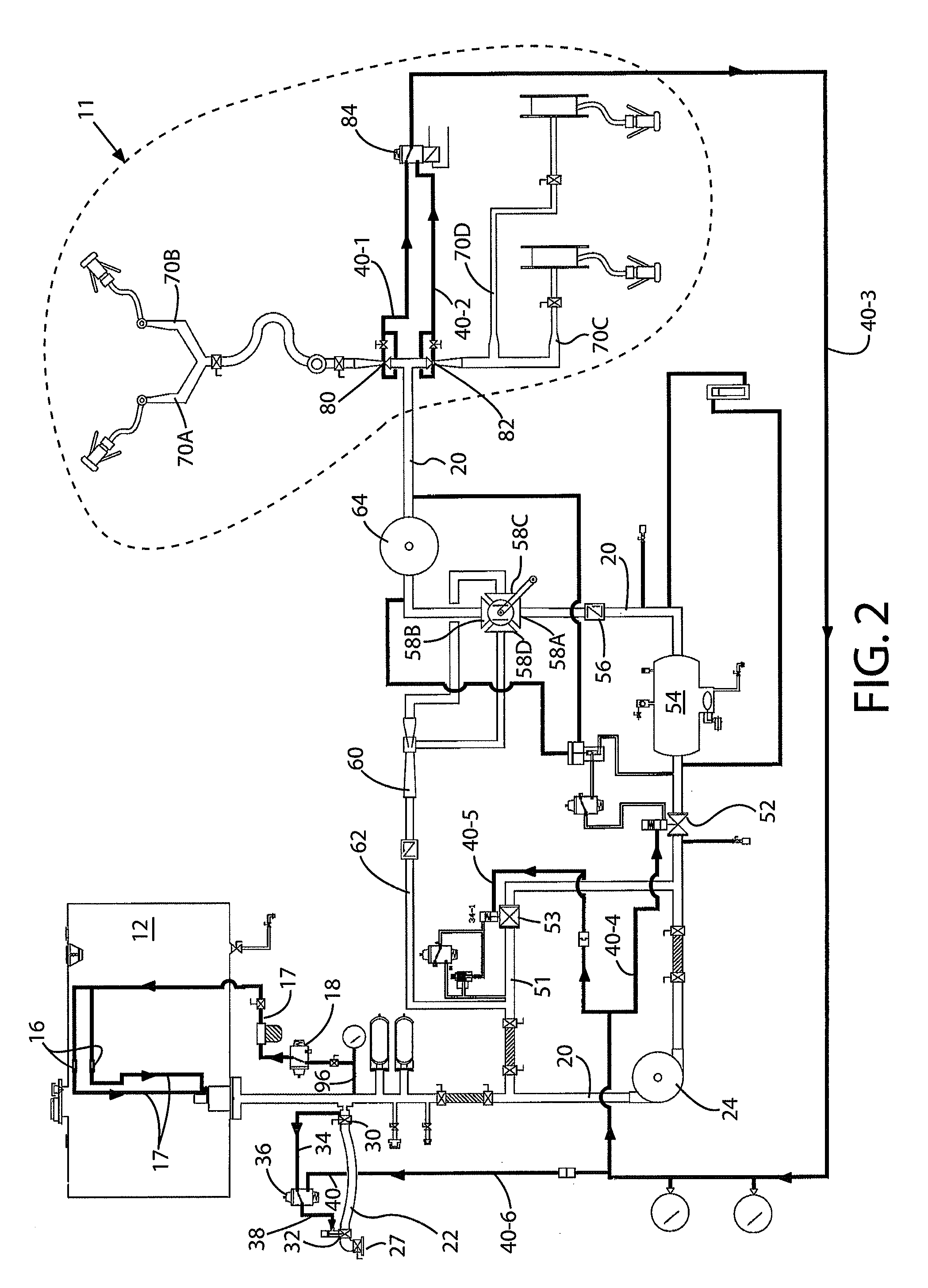
[0016]FIG. 1 depicts a schematic illustration of a fuel delivery system 10 of a fuel truck according to an exemplary embodiment of the invention. FIG. 2 depicts the fuel pressure feedback circuits of FIG. 1 and FIG. 3 depicts a compressed air circuit of FIG. 1. The fuel delivery system 10 that is shown in FIGS. 1-3 is configured to perform at least the following functions: (1) direct fuel from a hydrant pit valve (not shown) or other fuel source to a fuel tank of an aircraft (not shown), (2) direct fuel from the hydrant pit valve or other fuel source to an on-board fuel tank 12 of the fuel truck, (3) direct fuel from fuel tank 12 to a fuel tank of an aircraft, and (4) direct fuel from the fuel tank of an aircraft to fuel tank 12. This invention concerns the first two functions of system 10.

[0017]As an overview of FIG. 1, fuel delivery system 10 of a fuel truck includes a fuel delivery cir...


PUM

PropertyMeasurementUnit
pressureaaaaaaaaaa
pressureaaaaaaaaaa
pressureaaaaaaaaaa

Abstract

A fuel delivery system of an aircraft refueling vehicle that is configured to distribute fuel from a hydrant pit valve at an airport. The fuel delivery system includes a first hose including a coupler that is configured to be fluidly connected to a hydrant pit valve at an airport to receive fuel from the hydrant pit valve. A fuel passageway is fluidly coupled to the first hose. An on-board fuel tank is fluidly coupled to the fuel passageway. A second hose is fluidly coupled to the fuel passageway. The second hose includes a nozzle that is configured to be coupled to a refueling point on an aircraft to distribute fuel into a fuel tank of an aircraft. A valve is coupled to the fuel passageway to control the flow of fuel to and from the aircraft refueling vehicle.

Description

CROSS-REFERENCE TO RELATED APPLICATION[0001]This application claims priority to U.S. Provisional Patent Application No. 61 / 317,802, filed Mar. 26, 2010, the contents of which are incorporated by reference.FIELD OF THE INVENTION[0002]The invention relates to a method for distributing fuel from a hydrant pit valve at an airport directly to an aircraft, a method for delivering fuel from a hydrant pit valve to a fuel storage tank of a fuel truck, and a system for carrying out those methods.BACKGROUND OF THE INVENTION[0003]Most airports have dedicated oil depots (usually called “fuel farms”) where aviation fuel (Jet A or 100LL, for example) is stored prior to being discharged into aircraft fuel tanks. Fuel is transported from the oil depot to the aircraft either by a fuel truck having an on-board fuel tank (which is also known as a road tanker or a refueler) or via a fuel hydrant system that transports the fuel from the oil depot to a fueling apron of an airport. The fuel hydrant system ...

Claims


Application Information

Patent Timeline
Patent Type & Authority Patents(United States)
IPC IPC(8): B64F1/28B60P3/22B65B1/04
CPCB64F1/28Y10T137/6881
Inventor WATKINS, OWENSELL, EDWARD A.
Owner GENERAL TRANSERVICE
Why Eureka
Try Eureka