Arrangement of a stabilizer on a wheel suspension for motor vehicles

a technology for a stabilizer and a wheel suspension, which is applied in the direction of resilient suspensions, vehicle springs, interconnection systems, etc., can solve the problems of affecting the function of the stabilizer and the difficulty of removing it from the vehicle, and achieve the effect of enlarging the effective torsion length and stabilizing the abutment for bending moments

Active Publication Date: 2013-08-20
AUDI AG
View PDF27 Cites 7 Cited by
  • Summary
  • Abstract
  • Description
  • Claims
  • Application Information

AI Technical Summary

Benefits of technology

[0010]To provide a stable abutment for bending moments, each of the torsion bars may be supported for rotation in a bearing location of the superstructure, in particular in the region of the output lever. Each of the torsion bars can be extended beyond the bearing location with a projecting length, thereby enlarging its effective torsion length. To make use of the entire installation space available in the transverse direction of the vehicle, each torsion bar may have a projecting length that corresponds to the distance between the bearing location and the vehicle wheel in its neutral position minus a required movement clearance of the vehicle wheel. In this way, the vehicle wheel is prevented from making contact with the torsion bar when the toe angle / camber angle changes.

Problems solved by technology

The stabilizer is, on one hand, exposed to thermal stress when the vehicle is in operation which may impair its functionality.
On the other hand, the stabilizer is difficult to remove from the vehicle during service.

Method used


Image

  • Arrangement of a stabilizer on a wheel suspension for motor vehicles
  • Arrangement of a stabilizer on a wheel suspension for motor vehicles
  • Arrangement of a stabilizer on a wheel suspension for motor vehicles

Examples


Embodiment Construction

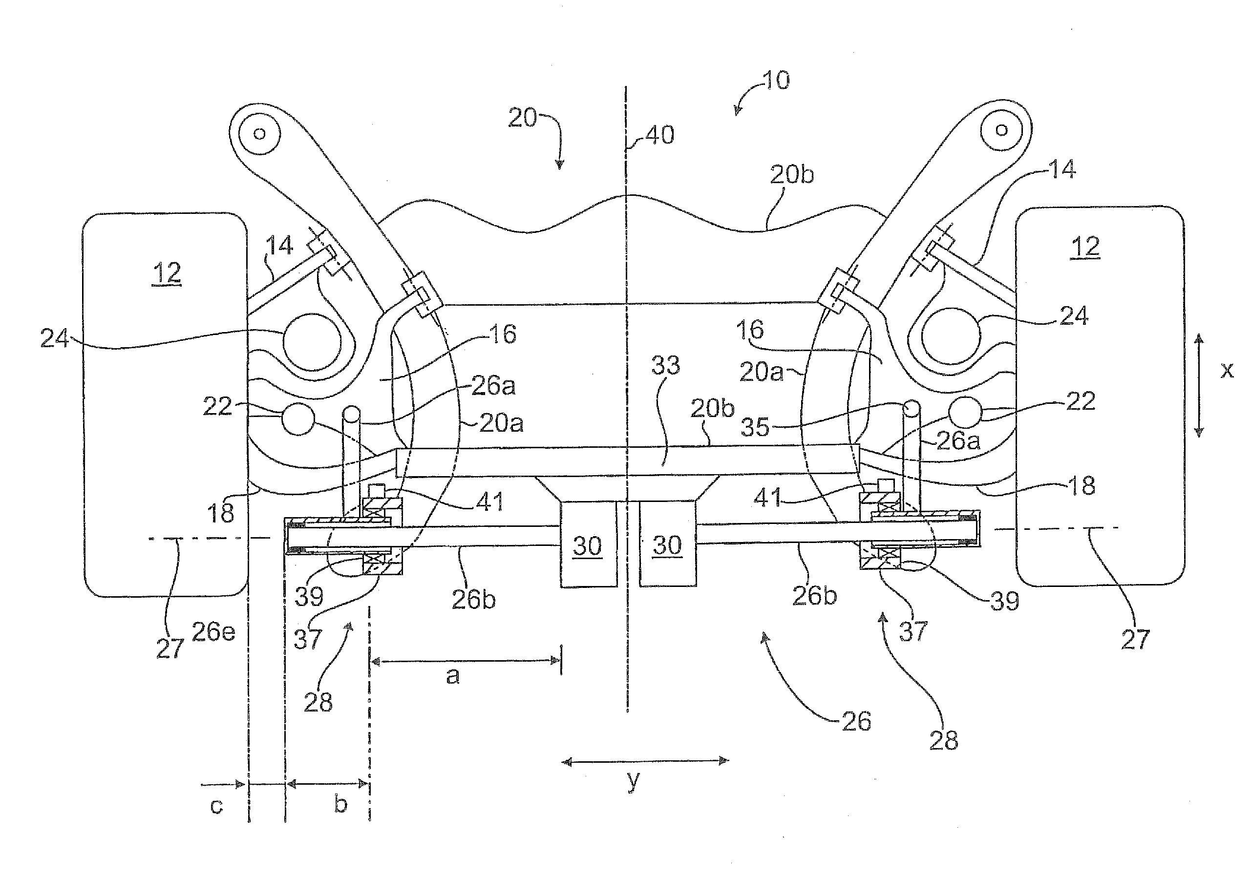
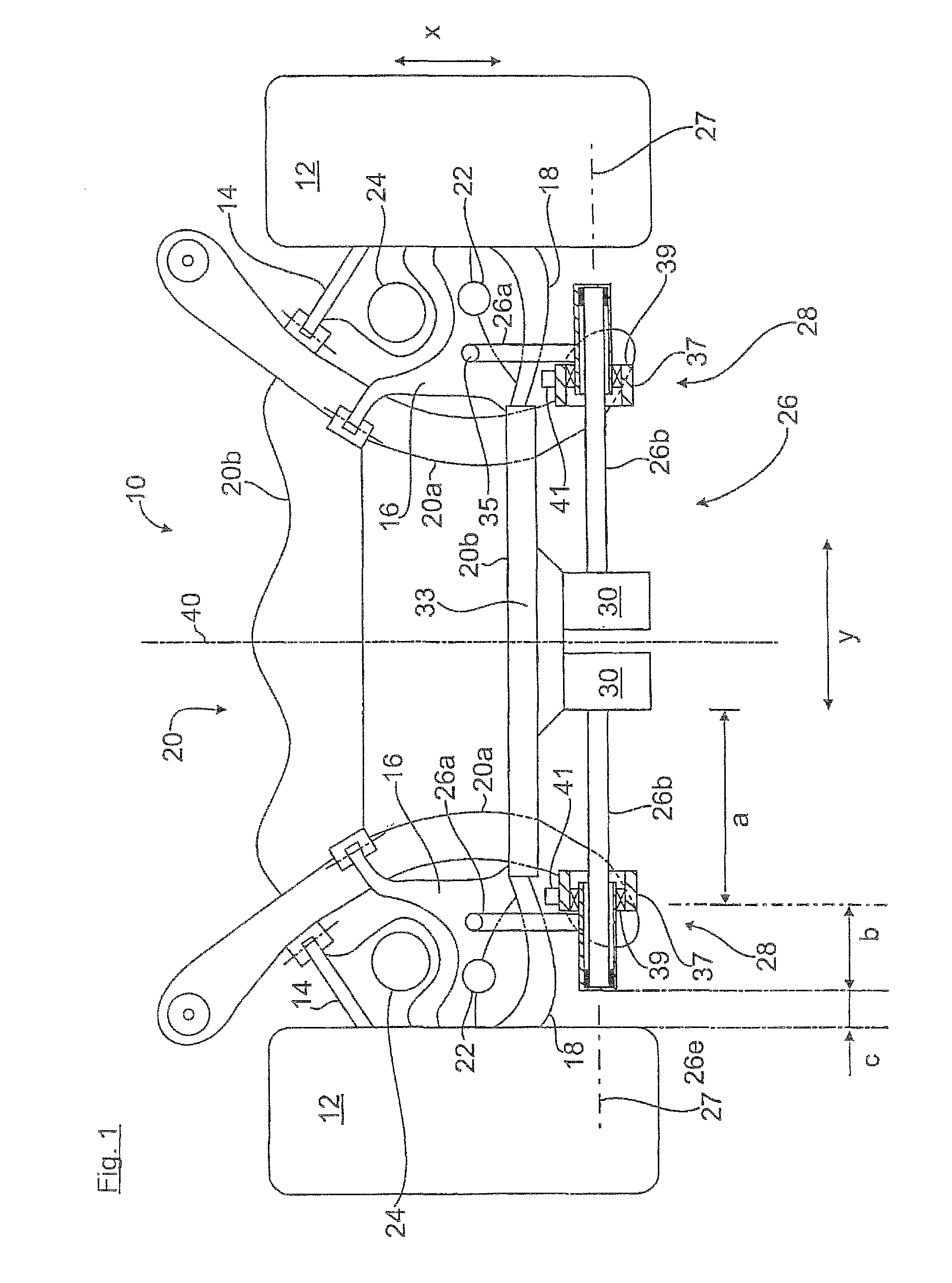
[0016]FIG. 1 shows in a simplified schematic diagram a rear wheel suspension 10 for the rear wheels 12 of a motor vehicle, wherein the wheel-guiding suspension arms 14, 16, 18, not shown in greater detail, are swingably mounted on the side of the wheel to a wheel carrier (not shown) and swingably mounted on the side of the superstructure to an auxiliary frame 20. The auxiliary frame 20 has, as shown, two side rails 20a and two crossbeams 20b and is mounted in a manner not shown on the superstructure of the motor vehicle by way of damping bearings.

[0017]In addition, a shock absorber 22 and a bearing spring 24 are arranged on each side in a conventional manner between the suspension arms 14, 18 and the superstructure of the motor vehicle. In a modified form, the wheel suspension 10 may also be designed as a wheel suspension for the steered front wheels of a motor vehicle.

[0018]Furthermore, according to FIG. 1, a substantially U-shaped two-part stabilizer 26 is supported for rotation o...


PUM


Abstract

The invention relates to an arrangement of a stabilizer (26), which is configured in two parts, on a wheel suspension for a motor vehicle, comprising torsion bars (26b) which are separated from each other and are each articulated on wheel suspension elements (16) by means of an output lever (26a) and can be co-rotated in the same or opposite direction by means of associated actuating devices (30), wherein each torsion bar (26b) is extended with a hollow shaft (26e) which encompasses the torsion bar (26b) in order to increase the effective torsion length, the output lever (26a) being formed on the hollow shaft. According to the invention, the torsion bar (26b) is mounted in a fixed bearing (59) in the actuating device (30) and in an axial loose bearing (26d) in the hollow shaft (26e).

Description

CROSS-REFERENCES TO RELATED APPLICATIONS[0001]This application is the U.S. National Stage of International Application No. PCT / EP2009 / 009235, filed Dec. 23, 2009, which designated the United States and has been published as International Publication No. WO 2010 / 083874 and which claims the priority of German Patent Application, Serial No. 10 2009 005 898.2, filed Jan. 23, 2009, pursuant to 35 U.S.C. 119(a)-(d).BACKGROUND OF THE INVENTION[0002]The invention relates to an arrangement of a stabilizer on a wheel suspension for motor vehicles.[0003]For example, DE 101 26 928 A1, DE 10 2004 002 550 A1 or DE 102 42 552 B4 disclose generic arrangements of two-part stabilizers with an actuating device for affecting the spring rates and the driving characteristics of motor vehicles. The roll behavior and banking of the motor vehicle can be reduced by adjusting the split torsion bars of the overall U-shaped stabilizer in opposite directions, or the tendency to slant, for example during braking,...

Claims


Application Information

Patent Timeline
Patent Type & Authority Patents(United States)
IPC IPC(8): B60G21/055
CPCB60G11/183B60G17/025B60G21/0555B60G17/0162B60G2200/184B60G2202/42B60G2204/1222B60G2204/418B60G2204/4232B60G2204/44B60G2204/45B60G2206/427B60G2206/82B60G2206/8201B60G2206/8207
Inventor OHLETZ, ARMINSCHMIDT, WALTER
Owner AUDI AG
Why Eureka
Try Eureka