Apparatus for driving three-phase brushless motor

a three-phase brushless motor and controller technology, applied in the direction of motor/generator/converter stopper, electronic commutator, dynamo-electric converter control, etc., can solve the problem of voltage being easily affected by noise, changing the rise time constant, and inconvenient to expand the circuit siz

Inactive Publication Date: 2002-11-14
SEKI KUNIO
View PDF0 Cites 7 Cited by
  • Summary
  • Abstract
  • Description
  • Claims
  • Application Information

AI Technical Summary

Benefits of technology

[0019] According to the apparatus of the aspect of the present invention, it is possible to detect the stop position of the rotor to a stator of the three-phase bushless motor, determine the phase stator winding to which the current is supplied first, and rotate the three-phase brushless motor in a desired direction, without using a hall element and providing such a circuit as a counter, an AD converter and so on therein.
[0022] Accordingly, when kickback voltages are generated in the second-phase stator winding and the third-phase stator winding at the same time, and compared with each other, it is possible to detect the stop position of the rotor to a stator of the three-phase brushless motor in a short time. That is, it is possible to be thought that the current is supplied from the first-phase stator winding to the second-phase stator winding and from the first-phase stator winding to the third-phase stator winding separately, and kickback times generated in the second-phase stator winding and the third-phase stator winding respectively are compared. However, when the current is supplied from the first-phase stator winding to the second-phase stator winding and from the first-phase stator winding to the third-phase stator winding at the same time, it is possible to compare the lengths of the kickback times efficiently.
[0024] Accordingly, it is possible to detect the stop position of the rotor exactly. As a result, because the phase stator winding to which the current is supplied first is determined on the basis of the detected stop position, it is possible to rotate the rotor in a desired direction quickly.
[0026] Accordingly, it is possible to prevent the rotor from shifting, and detect the stop position of the rotor more exactly.

Problems solved by technology

As a result, because the back motion may not only have an effect on a driving time of the motor, but also do fatally damage the motor itself or another structure as that depends on the uses thereof, it is necessary to prevent the back motion from occurring as much as possible.
However, because the change of the rise time constant of the current is quite little, and the current can not be read directly, it is necessary to transform from the current to a voltage once.
However, because the transformed voltage is a small value from several tens mV to several hundreds mV, the voltage has a fault in being easily affected by a noise.
Further, because various circuits such as a counter for measuring the time, an AD converter or a comparator for comparing voltages, and so on are required to compare the changes of the rise time constant of the current, there occurs an inconvenient state wherein a size of the circuit is expanded.
However, when the current is supplied from the first-phase stator winding to the second-phase stator winding and from the first-phase stator winding to the third-phase stator winding at the same time, it is possible to compare the lengths of the kickback times efficiently.

Method used


Image

  • Apparatus for driving three-phase brushless motor
  • Apparatus for driving three-phase brushless motor
  • Apparatus for driving three-phase brushless motor

Examples


Embodiment Construction

[0036] Hereinafter, a preferred embodiment of the present invention will be explained with reference to figures, as follows.

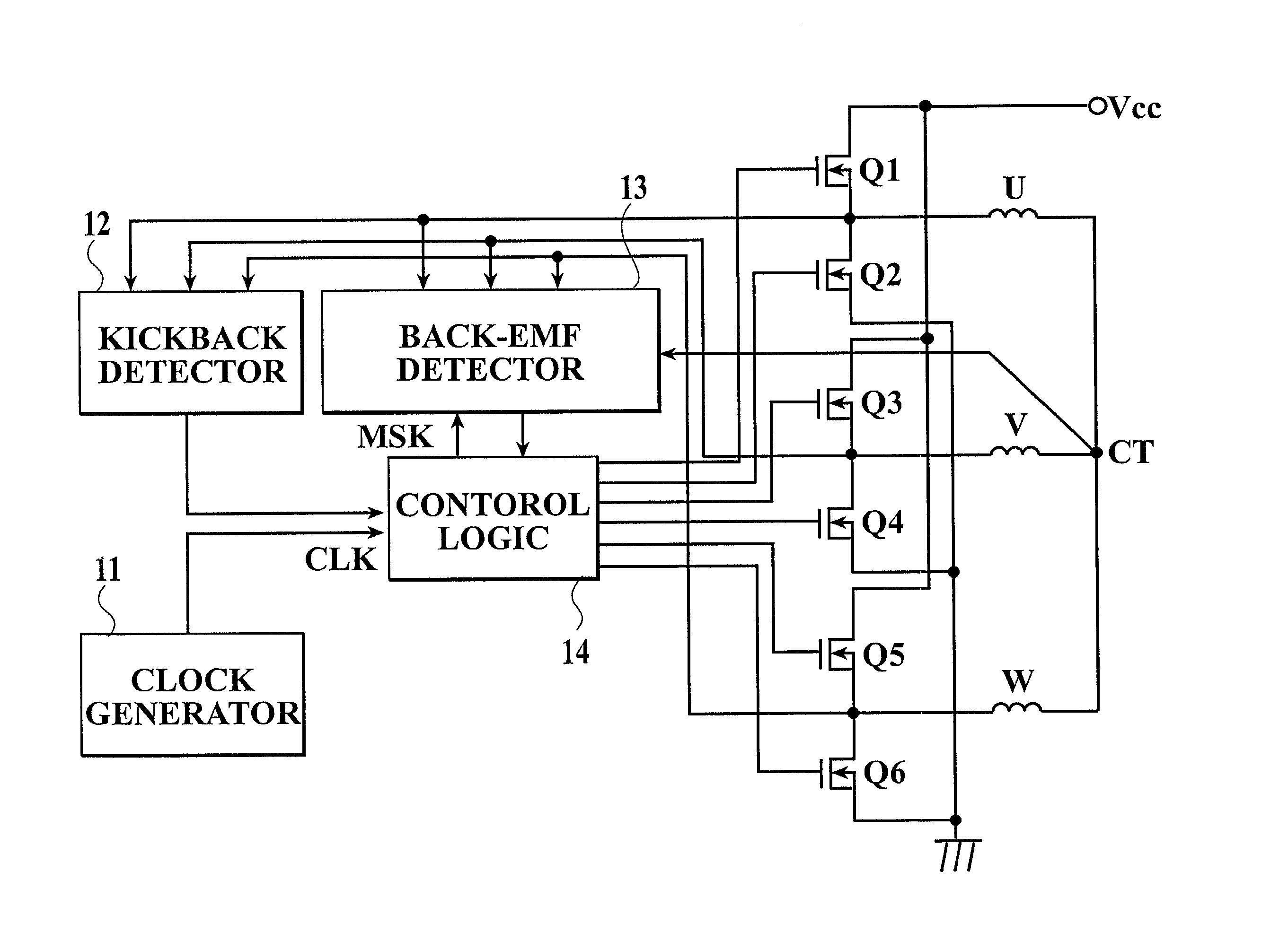
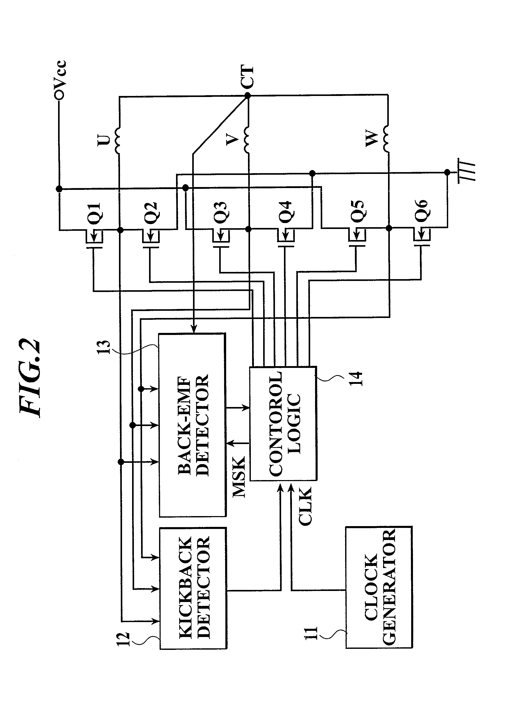
[0037] FIG. 2 is a block diagram showing an exemplary construction of a circuit for driving a three-phase full-wave drive brushless motor according to the present invention.

[0038] The reference characters "U", "V" and "W" denote stator coils comprising windings which are wound on a core of a stator, and "Q1" to "Q6" denote output transistors for supplying a drive current to the stator coils U, V and W. The reference numeral "11" denotes a clock generator for generating a necessary clock signal for the circuit to drive, "12" denotes a kickback detector for detecting a kickback voltage generated when the stator coils U, V and W are turned off, to determine a stop position of a rotor magnet, "13" denotes a back-EMF detector (a back electromagnetic force detector) for detecting a position of the rotor magnet rotating on the basis of a zero-cross point of a back ele...


PUM


Abstract

An apparatus for driving a three-phase brushless motor, which has a simple structure easily unaffected by a noise and so on and requiring no counter, no AD converter and so on, and which can exactly determine a stop position of a rotor to a stator of the motor, determine a phase stator winding from which a current-carrying is started, and correctly rotate the rotor in a desired direction when the motor is driven. The apparatus supplies a short pulse current from one phase stator winding to another two phase stator windings so that the rotor is not driven when the rotor stops, and determines the stop position of the rotor on the basis of a difference of kickback times caused by a difference of inductances of the phase stator windings changing subtly according to a difference of the stop position of the rotor.

Description

[0001] 1. Field of the Invention[0002] The invention relates to a controlling technique for driving a three-phase brushless motor, and in particular to an effective technique in a detecting system of a stop position of a rotor and a starting system when the rotor starts rotating. For example, the invention relates to an effective technique in a controlling technique for driving a spindle motor for rotating a storage medium of a disc type storage apparatus such as a hard disc apparatus. Hereinafter, the storage medium will be called a magnetic disc.[0003] 2. Description of Related Art[0004] In order to satisfy a demand for such a disc type storage apparatus as a hard disc apparatus to write data in and read data from a magnetic disc at as high speed as possible, that is, in order to satisfy a great demand for higher speed data access, it is necessary to drive a spindle motor for rotating the magnetic disc at higher speed. Further, in order to satisfy a great demand that a driving app...

Claims


Application Information

Patent Timeline
Patent Type & Authority Applications(United States)
IPC IPC(8): H02P6/18H02P6/06H02P6/08H02P6/182H02P6/22
CPCH02P6/22
Inventor SEKI, KUNIO
Owner SEKI KUNIO
Why Eureka
Try Eureka