Clamp device

a technology of a clamping device and a clamping plate, which is applied in the direction of positioning apparatuses, metal-working machine components, manufacturing tools, etc., to achieve the effect of simple structure and excellent versatility in us

Active Publication Date: 2013-08-27
PASCAL ENG
View PDF20 Cites 9 Cited by
  • Summary
  • Abstract
  • Description
  • Claims
  • Application Information

AI Technical Summary

Benefits of technology

[0012]According to the clamp device of the present invention, since the grip member, the clamp rod, and the support mechanism are provided at one end portion of the main body member, and an axis of the grip member and the clamp rod is offset from an axis of the clamping fluid pressure cylinder in the direction orthogonal to the clamp rod, accordingly, when clamping a hole in an external circumferential flange portion of a workpiece, it is possible to clamp the workpiece with a clamp device in a state which the vicinity of the one end of the main body member and the grip member, the clamp rod, and the support mechanism are arranged so as to correspond to the hole in the external circumferential flange portion.
[0013]In this case, by the greater portion of the main body member of the clamp device being positioned more to the outside than the contour of the workpiece, it is possible reliably to prevent interference between the main body member and portions other than the external circumferential flange portion of the workpiece. A workpiece may be clamped if it is a workpiece such as one having a receptacle portion that bulges downwards from the interior of an external circumferential flange portion; or a workpiece of a flat plate type can also be clamped in a similar manner to that in the case of a prior art type clamp device. In other words, this clamp device is capable of clamping workpieces of various shapes and structures, and is excellent from the point of view of versatility in use.

Problems solved by technology

When performing machine processing over the entire surface of a workpiece or around the entire external circumference thereof, a clamp device of the type described above (a so-called hole clamp) is employed, since it is not possible to employ a clamp device of the type that presses from above with a pressing tool on an edge portion of the workpiece.

Method used


Image

  • Clamp device
  • Clamp device
  • Clamp device

Examples


embodiment 1

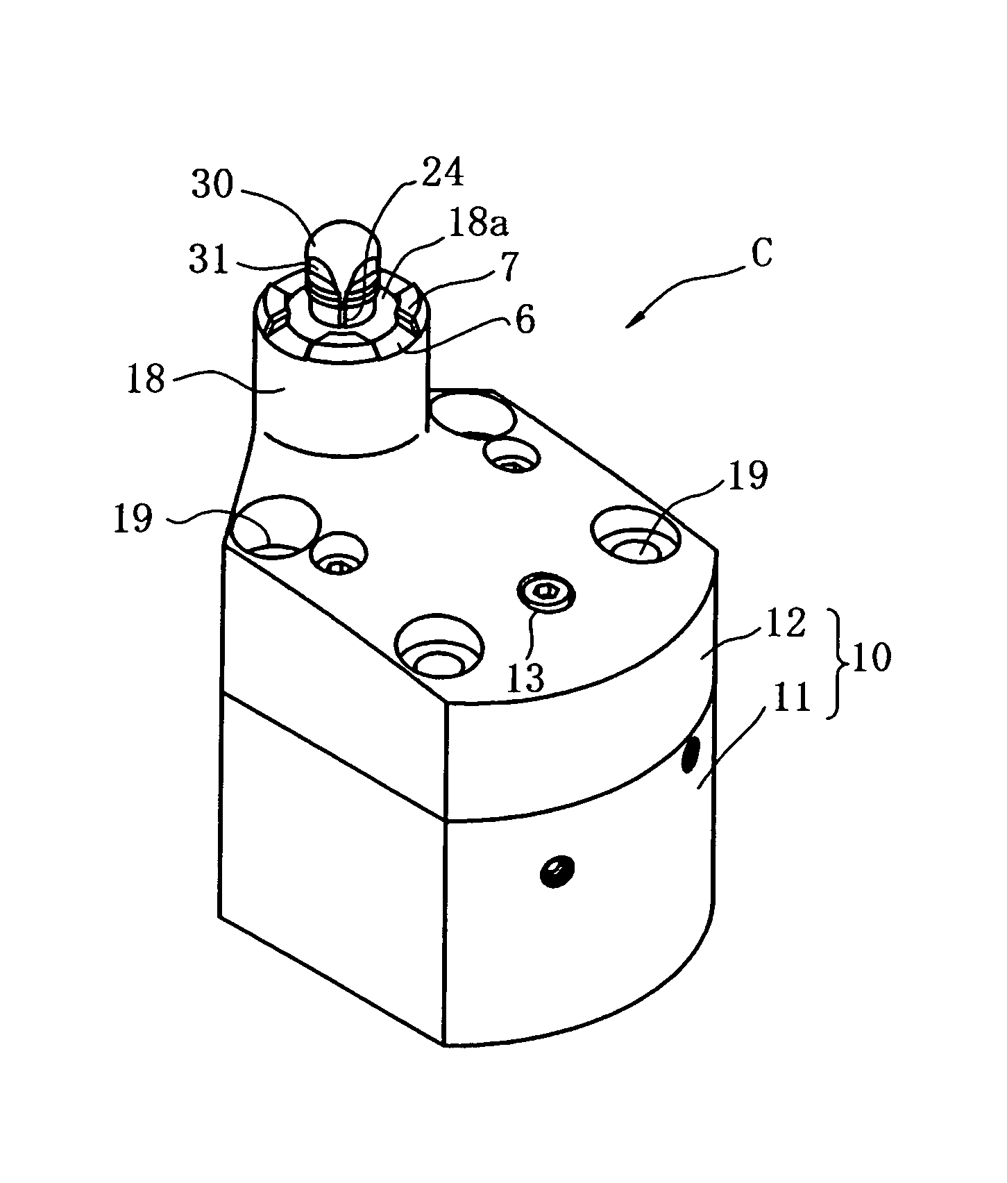
[0076]In the following, Embodiment 1 of the present invention will be explained based on the drawings. The present invention presents a clamp device of a type in which a grip claw portion of a grip member is engaged to clamp with a hole in a workpiece (i.e. “hole clamp”).

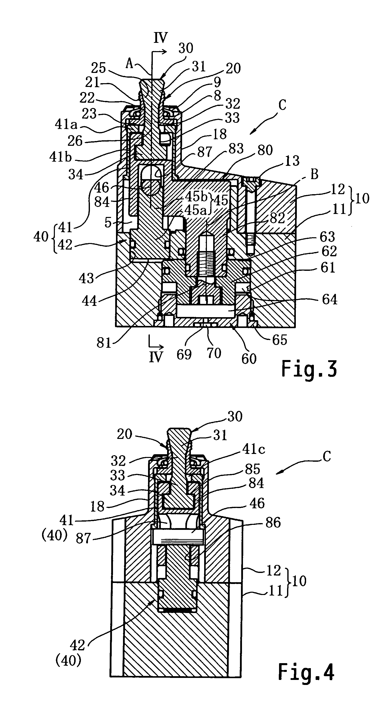
[0077]As shown in FIGS. 1 to 5, this clamp device C comprises a main body member 10 to be a clamp main body, an annular grip member 20, a clamp rod 30 having a tapered shaft portion 31, a support mechanism 40, a clamping hydraulic cylinder 60, and so on. The grip member 20, the clamp rod 30, and the support mechanism 40 have a common vertical axis A.

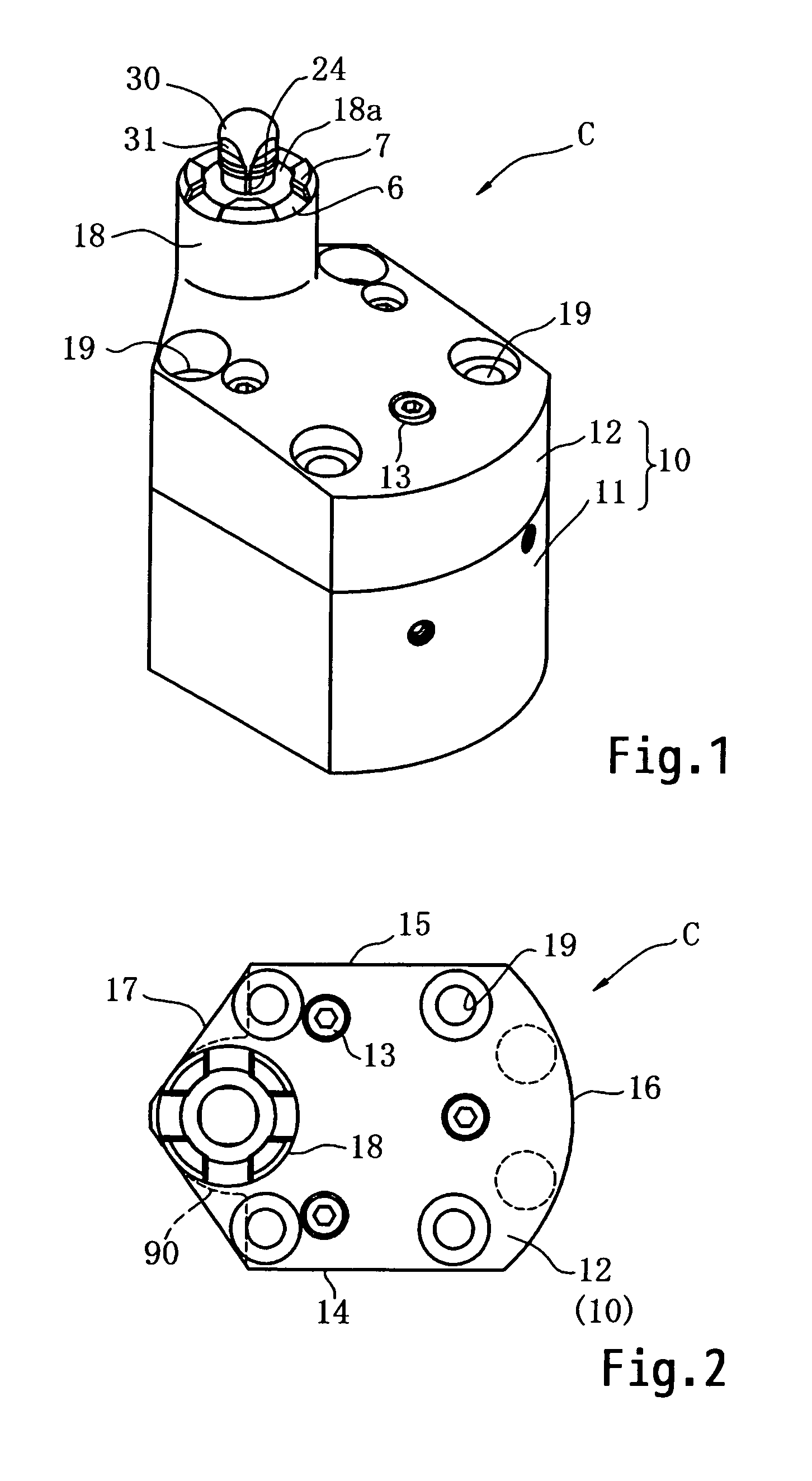
[0078]The main body member 10 is for installing (attaching) the grip member 20, the clamp rod 30, the support mechanism 40, and the lamping hydraulic cylinder 60. This main body member 10 comprises a lower main body member 11 and an upper main body member 12 that is fixed on the lower main body member 11 by three bolts 13.

[0079]In plan view, the main body member 10 has a...

embodiment 2

[0109]As shown in FIGS. 10 to 15, since a support mechanism 40A that is different from that of Embodiment 1 is provided to this clamp device CA, principally this support mechanism 40A will be explained, while the same reference symbols will be affixed to structural elements that are the same as ones in Embodiment 1, with the explanation thereof being omitted.

[0110]The supporting hydraulic cylinder 42A comprises a cylinder bore 43 formed in the main body member 10, a hydraulic chamber 44 at one end portion of the cylinder bore 43, and a piston member 45A that receives the hydraulic pressure in this hydraulic chamber 44. The piston member 45A comprises a piston portion 45c and a piston rod 45d, whose horizontal section is half circular or U shaped, which extends from this piston portion 45c towards the grip member 20 and supports the base end (i.e. the lower end) of the support member 41. The piston rod 45d is engaged to the outer surface of the lower portion of the second vertical sh...

embodiment 3

[0118]As shown in FIGS. 16 to 20, since a support mechanism 40B and an L shaped link member 80B and a clamping hydraulic cylinder 60B that are different from those of Embodiments 1, 2 are provided in this clamp device CB, principally this support mechanism 40B, this L shaped link member 80B, and the clamping hydraulic cylinder 60B will be explained, while the same reference symbols will be affixed to structural elements that are the same as those in Embodiments 1, 2, with the explanation thereof being omitted.

[0119]This clamping hydraulic cylinder 60B comprises a cylinder bore 61B, a piston member 62B installed in the cylinder bore 61B, a clamping hydraulic chamber 63B at the upper end portion of the cylinder bore 61B, and a hydraulic chamber for clamp release 64B at the lower end portion of the cylinder bore 61B. Hydraulic passages 66B, 67B and a hydraulic pressure supply port 68B are provided for supplying hydraulic pressure to the clamping hydraulic chamber 63B, and this hydrauli...


PUM


Abstract

A clamp device includes a support mechanism that supports a grip member when expanding the diameter thereof, a clamping hydraulic cylinder that can drive the grip member and a clamp rod axially forwards and backwards (up and down), and a main body member to which the grip member, the clamp rod, the support mechanism, and the clamping hydraulic cylinder are mounted, with the grip member, the clamp rod, and the support mechanism being positioned at one end portion of the body member, and with the common axis of the grip member and the clamp rod being offset from the axis of the clamping hydraulic cylinder in a direction orthogonal to the clamp rod.

Description

TECHNICAL FIELD[0001]The present invention relates to a clamp device, and in particular relates to a clamp device for clamping a workpiece by expanding the diameter of grip claw portions of a grip member in a hole in the workpiece to engage it, and by pulling it against a seating surface.BACKGROUND TECHNOLOGY[0002]When performing machine processing over the entire surface of a workpiece or around the entire external circumference thereof, a clamp device of the type described above (a so-called hole clamp) is employed, since it is not possible to employ a clamp device of the type that presses from above with a pressing tool on an edge portion of the workpiece. With such a clamp device, a seating surface or surfaces on which the workpiece is to be seated is formed at an upper end portion of a clamp main body that is shaped as a block, so as to surround a grip member; and when the workpiece is to be loaded: the workpiece is mounted on this seating surface and supported thereon; a grip ...

Claims


Application Information

Patent Timeline
Patent Type & Authority Patents(United States)
IPC IPC(8): B23Q3/08B23Q3/00B25B3/00B25B1/14
CPCB23Q1/009B25B5/087B23Q3/06
Inventor KAWAKAMI, TAKAYUKI
Owner PASCAL ENG
Why Eureka
Try Eureka