Device for reducing vibration generated by rotorcraft rotor, and rotorcraft provided with such device

a technology of reducing vibration and rotorcraft, which is applied in the direction of propellers, propulsive elements, water-acting propulsive elements, etc., can solve the problems of not being able to adapt to frequencies, particularly perceptible vibration, and heavy devices of the first type, so as to reduce vibration, reduce vibration, and not require time-consuming maintenance actions

Active Publication Date: 2013-08-27
SANDIA +1
View PDF10 Cites 3 Cited by
  • Summary
  • Abstract
  • Description
  • Claims
  • Application Information

AI Technical Summary

Benefits of technology

[0044]An object of the present invention is thus to propose a device for reducing the vibration generated by a rotorcraft rotor while avoiding the above-mentioned limitations, the device making it possible to reduce vibration at a high frequency without giving rise to high levels of drag and optionally not requiring time-consuming maintenance actions.
[0049]As a result the heavy elements can generate vibration at high frequencies, while being contained in a small space in the immediate proximity of the axis of rotation of the rotor. This is unlike the solution proposed in document FR 2 768 995, which is relatively bulky because of the pendular movements of the oscillating bodies used.
[0061]This combination, which is not a mere juxtaposition, enables vibration at a high frequency to be reduced, while minimizing generation of drag by having the casing present.
[0062]Furthermore, this combination can also minimize the maintenance actions that need to be performed.
[0064]Thus, the casing may be partially filled with a lubricant, such as oil. This lubricant enables the device to be lubricated, and in particular enables the rollers to be lubricated so as to avoid premature wear, without requiring frequent intervention on the part of an operator.

Problems solved by technology

The parasitic forces then induce vibration that propagates to the airframe of the rotorcraft, which vibration is particularly perceptible in the cockpit of the rotorcraft.
Nevertheless, those devices of the first type are sometimes heavy.
Unfortunately, since devices of the first type are designed to attenuate vibration at a given frequency, such devices of the first type are not capable of adapting to frequencies that vary.
In the first solution, the first distance needs to be long, which appears to be impossible as a result of the increase in mass and drag that results therefrom.
Nevertheless, that second solution is difficult to apply since it would be appropriate to use hinges that are over-dimensioned in order to support the heavy element.
Nevertheless, in a helicopter provided with a large number of blades, the first distance continues to be long.
Furthermore, it should be observed that the friction between a heavy element and the associated rollers, and between a branch of the support and the rollers associated therewith tends to damage the device as a whole, thereby giving rise to degradation in its performance.
In order to remedy that, an operator needs to lubricate the device for each flight, thereby giving rise to obvious difficulties.
However, the device gives rise to non-negligible levels of aerodynamic drag.

Method used


Image

  • Device for reducing vibration generated by rotorcraft rotor, and rotorcraft provided with such device
  • Device for reducing vibration generated by rotorcraft rotor, and rotorcraft provided with such device
  • Device for reducing vibration generated by rotorcraft rotor, and rotorcraft provided with such device

Examples


Embodiment Construction

[0084]Elements shown in more than one figure are given the same references in each of them.

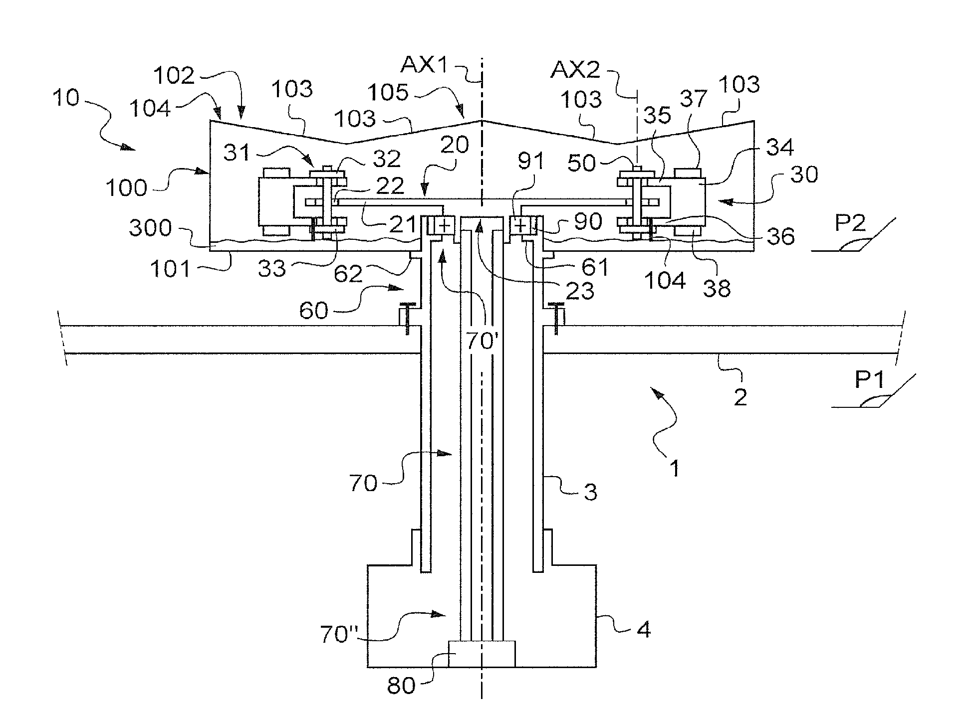
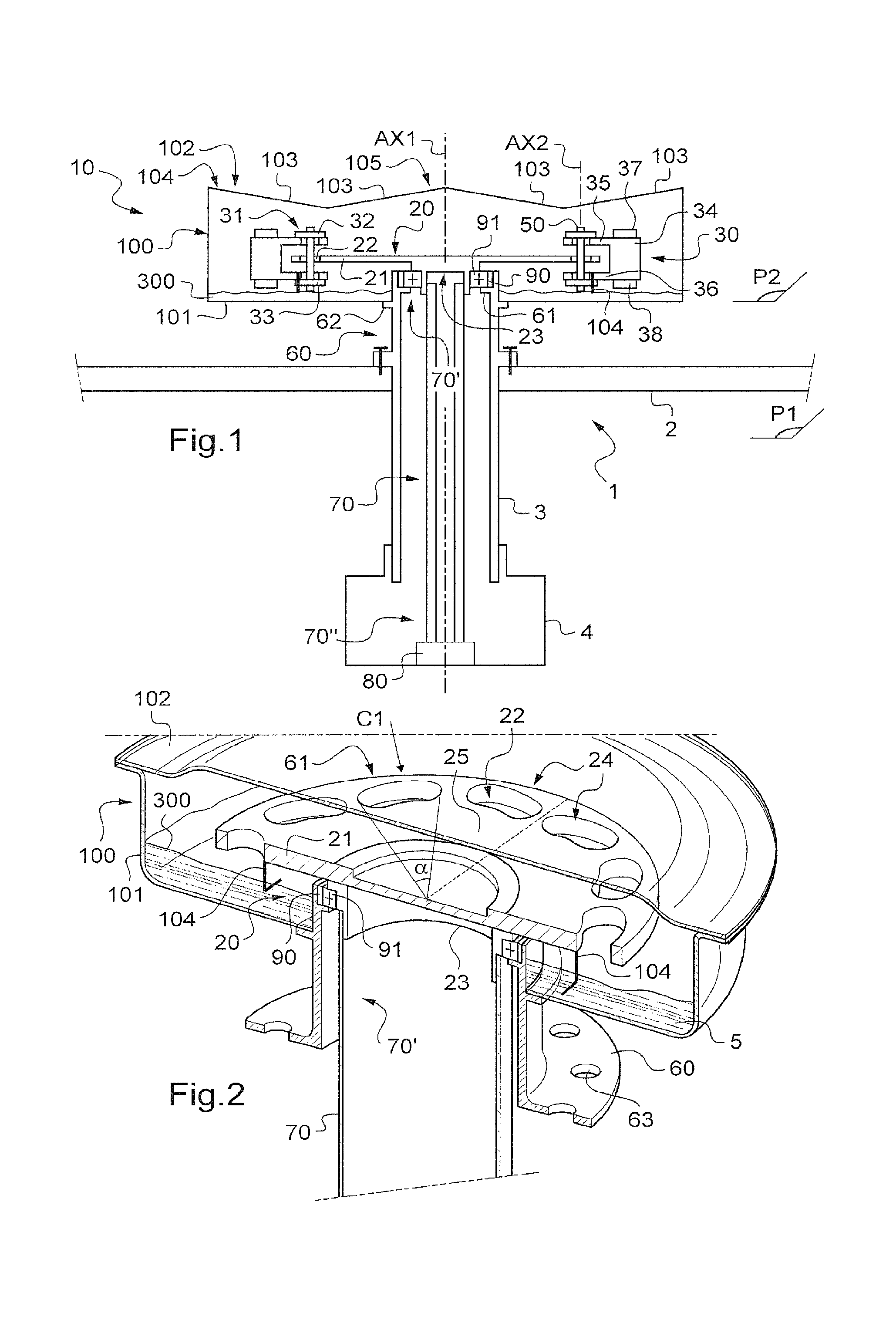
[0085]FIG. 1 is a diagrammatic section of a device 10 for reducing the vibration of a main rotor 1 of a rotorcraft.

[0086]The main rotor 1 comprises a hub 2 extending in a first plane P1 to carry blades (not shown). In order for the blades to generate lift, the hub 2 is set into rotation by a terminal first stage of a power gearbox 4 via a rotor mast 3, the rotor mast being constrained to rotate about the axis of rotation AX1 with the hub 2 and with the terminal first stage of the power gearbox 4.

[0087]The movements of the blades while rotating about the axis of rotation AX1 cause vibration to be created that can be felt in the airframe of a rotorcraft by the occupants of the rotorcraft.

[0088]Consequently, the rotorcraft includes a device 10 suitable for reducing the vibration, the device 10 being a pendular resonator.

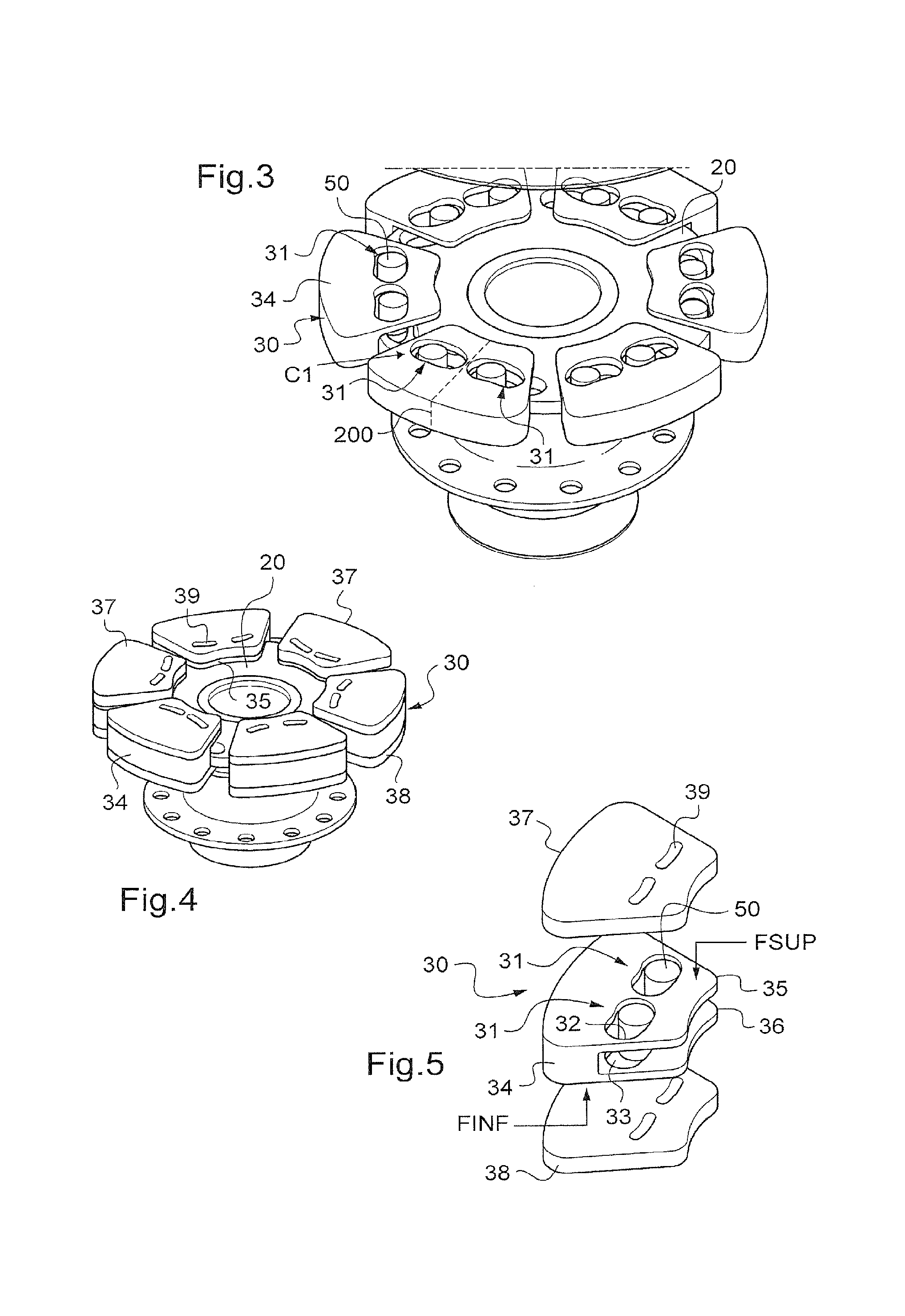
[0089]The device 10 has heavy elements 30 arranged on a support 20, and more ...


PUM


Abstract

A device (10) for reducing vibration of a main rotor (1) having a support (20) and a plurality of heavy elements (30) and of rollers (50). Each heavy element (30) includes two first openings (31) respectively at least partially in registration with two second openings (22) of the support (20. Each roller (50) passes through a first opening (31) and a second opening (22). The device (10) has link means (60) for connecting the support (20) to the hub (2). A drive shaft (70) and a drive means (80) rotate at a first speed of rotation (V1) greater than a second speed of rotation (V2) of the hub (2). The drive shaft (70) rotates about an axis of rotation (AX1) of the support (20). The link means (60) is connected to the support (20) by a link member (90) enabling the support (20) to rotate about the axis of rotation (AX1) relative to the link means (60).

Description

CROSS-REFERENCE TO RELATED APPLICATION[0001]This application claims the benefit of application no. FR 09 05167, filed Oct. 27, 2009, the disclosure of which is incorporated herein by reference.FIELD OF THE INVENTION[0002]The invention relates to a device for reducing the vibration generated by a rotorcraft rotor, and to a rotorcraft provided with such a device.BACKGROUND OF THE INVENTION[0003]In operation, a lift rotor of a rotorcraft, e.g. a main lift and propulsion rotor of a helicopter, generates parasitic forces at the head of the lift rotor. The parasitic forces then induce vibration that propagates to the airframe of the rotorcraft, which vibration is particularly perceptible in the cockpit of the rotorcraft.[0004]To mitigate that drawback, devices have been made for attenuating the vibration that is generated, sometimes referred to as rotor head resonators.[0005]In a first type of device, described in particular in document FR 2 749 901, use is made of a flapping weight that ...

Claims


Application Information

Patent Timeline
Patent Type & Authority Patents(United States)
IPC IPC(8): B64C27/32
CPCB64C27/001B64C2027/005Y10T74/2128F16F15/145
Inventor MANFREDOTTI, THOMAS
Owner SANDIA
Why Eureka
Try Eureka