Injection mold

a mold and injection technology, applied in the field of injection molds, can solve the problems of increasing and achieve the effect of reducing the defective rate of the product and reducing the manufacturing cost of the produ

Inactive Publication Date: 2013-08-27
CHENG UEI PRECISION IND CO LTD
View PDF20 Cites 5 Cited by
  • Summary
  • Abstract
  • Description
  • Claims
  • Application Information

AI Technical Summary

Benefits of technology

[0007]As described above, the inserting space is wider than the inserting perforation in diameter for facilitating the second sliding block away from the male core ahead of the first sliding block so as to make the inclined lump of the second sliding block and the straight bar of the first sliding block parted from the product separately. Furthermore, the tilt angle of the inclined lump is the same as that of the inclined guiding surface to make the second sliding block slide away from the male core along the inclined guiding surface to make the inclined lump of the second sliding block smoothly parted from the product, and then, the first sliding block slides away from the male core on the top of the male mold to make the straight bar parted from the product steadily. So, the product is effectively unloaded from the injection mold to ensure a successful production of the product to lower defective rate of the product and decrease manufacturing cost of the product.

Problems solved by technology

However, the sliding block just slides away from the male core along a longitudinal direction on the male mold to pull the straight bar out of the straight gap and the inclined lump out of the inclined groove simultaneously, in that event, the inclined lump is apt to be damaged on account of being pulled out from the inclined groove along the longitudinal direction that results in a higher defective rate of the product and increases manufacturing cost of the product.

Method used


Image

  • Injection mold
  • Injection mold
  • Injection mold

Examples


Embodiment Construction

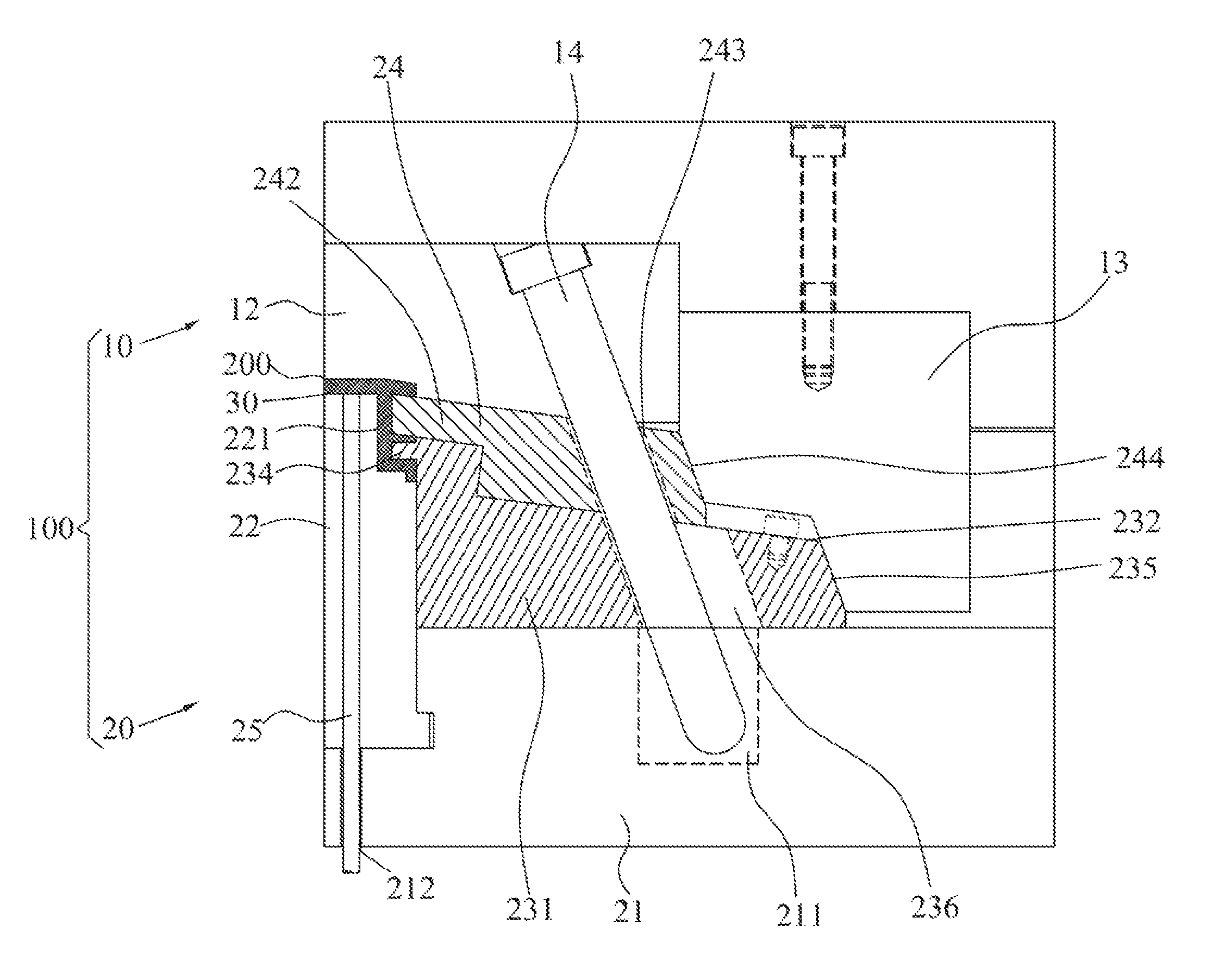
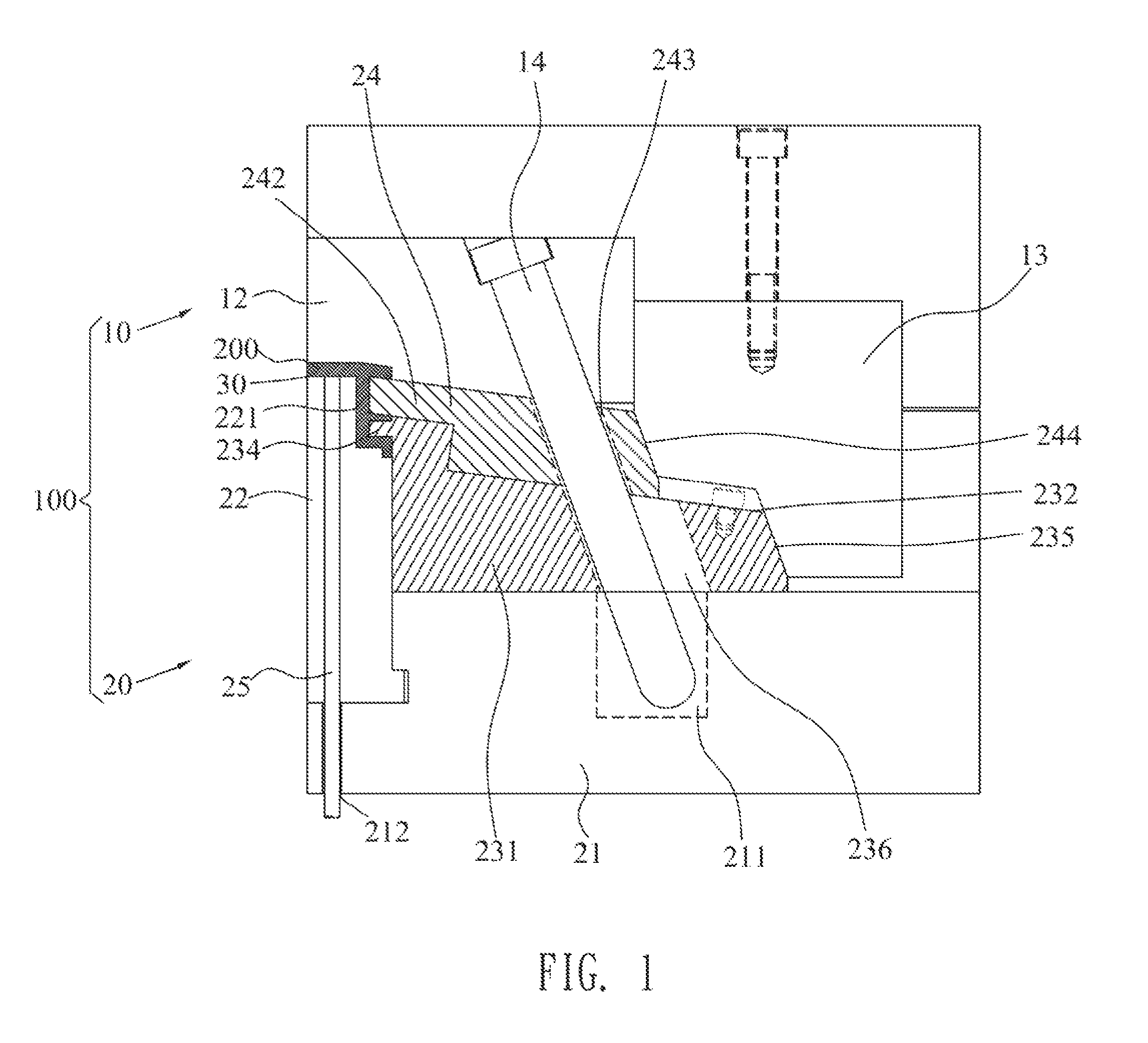
[0014]With reference to FIG. 1 and FIG. 2, an embodiment of an injection mold 100 in accordance with the present invention is shown. The injection mold 100 adapted for molding a product 200 includes a female mold 10 and a male mold 20. The product 200 has an inclined groove 210 at an upper portion of a side thereof and a straight gap 220 at a lower portion of the side thereof and spaced from the inclined groove 210.

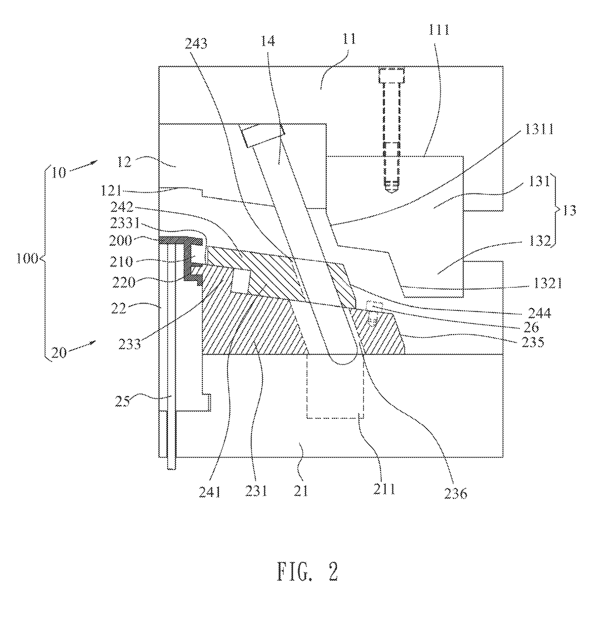
[0015]Referring to FIG. 1, FIG. 2 and FIG. 3, the female mold 10 includes a female mold plate 11, a female core 12 mounted in a middle of a bottom of the female mold plate 11, a fastening block 13 and an inclined pillar 14. One side of the bottom of the female mold plate 11 defines a fastening groove 111. A middle of a bottom of the female core 12 is cut off to form a slot 121. The fastening block 13 includes a first fastening block 131 and a second fastening block 132 extending downward from one end of a bottom of the first fastening block 131. A lower portion of a side ...


PUM

PropertyMeasurementUnit
angleaaaaaaaaaa
diameteraaaaaaaaaa
thermoplasticaaaaaaaaaa

Abstract

An injection mold for molding a product which has an inclined groove and a straight gap at a side thereof includes a female mold and a male mold. The female mold includes a female core and an inclined pillar mounted in the female mold. The male mold includes a male core, a first sliding block and a second sliding block. The first sliding block is slidably mounted on the male mold, and has an inclined guiding surface. The second sliding block is slidably mounted on the inclined guiding surface. When the injection mold is opened, the second sliding block is smoothly parted from the product along the inclined guiding surface to form the inclined groove, and then, the first sliding block is parted from the product to form the straight gap under the action of the inclined pillar.

Description

BACKGROUND OF THE INVENTION[0001]1. Field of the Invention[0002]The present invention generally relates to an injection mold, and more particularly to an injection mold capable of unloading a product from the injection mold effectively.[0003]2. The Related Art[0004]In general, an injection mold for molding a product includes a male mold and a female mold. The product has an inclined groove at an upper portion of a side thereof and a straight gap at a lower portion of the side thereof. The male mold includes a male core mounted in a middle of a top of the male mold, and a sliding block. The sliding block has an inclined lump extended slantwise from an upper portion of a side of the sliding block, and a straight bar extended sideward from a lower portion of the side of the sliding block. The sliding block is slidably mounted on one side of the top of the male mold with the inclined lump and the straight bar facing to the male core. When the injection mold is closed, a shaping chamber ...

Claims


Application Information

Patent Timeline
Patent Type & Authority Patents(United States)
IPC IPC(8): B29C45/44
CPCB29C45/332B29C45/44
Inventor WANG, XIAN-YUNWU, XIAO-PINGCHIANG, KUN-HSUEHGONG, WEN-PENGLI, JIAN-MING
Owner CHENG UEI PRECISION IND CO LTD
Why Eureka
Try Eureka