Lens barrel and imaging apparatus

a technology of lens barrel and imaging apparatus, which is applied in the direction of mountings, instruments, cameras, etc., can solve the problems of low degree of freedom of design in arrangement, poor light shielding property of conventional lens barrel for external light, and light may affect the shot image, so as to achieve the effect of increasing the relative distance between the respective lens groups

Inactive Publication Date: 2013-08-27
CANON KK
View PDF13 Cites 2 Cited by
  • Summary
  • Abstract
  • Description
  • Claims
  • Application Information

AI Technical Summary

Benefits of technology

[0012]With this arrangement, the light-shielding property of the interior of the lens barrel against external light penetrating into the lens barrel becomes high, and the degree of freedom of design relating to the arrangement of the interlocking section for the cam ring can be improved.
[0014]According to the present invention, a first lens group and a second lens group are cam-engaged with and held by two separate cam members, respectively, these cam members are guided by a third cam member, and the third cam member is cam-engaged with and supported by the supporting member. With this arrangement, the variation in the relative distance between the respective lens groups is increased.

Problems solved by technology

A conventional lens barrel has a poor light-shielding property for external light, and a low degree of freedom of design in the arrangement of the interlocking section for a cam ring.
Hence, when external light that is penetrated into the lens barrel has passed through the outer periphery of the cam ring to reach the imaging element, there is a possibility that such light may affect a shot image.
Additionally, the arrangement of the interlocking section, which moves in association with adjacent members, of the cam ring is limited, resulting in a reduction in the degree of freedom of design.
Therefore, it is difficult to balance reducing the length of the lens barrel in the optical axis direction in a retracted state as much as possible and obtaining a large change in the relative distance during lens driving.

Method used


Image

  • Lens barrel and imaging apparatus
  • Lens barrel and imaging apparatus
  • Lens barrel and imaging apparatus

Examples


Embodiment Construction

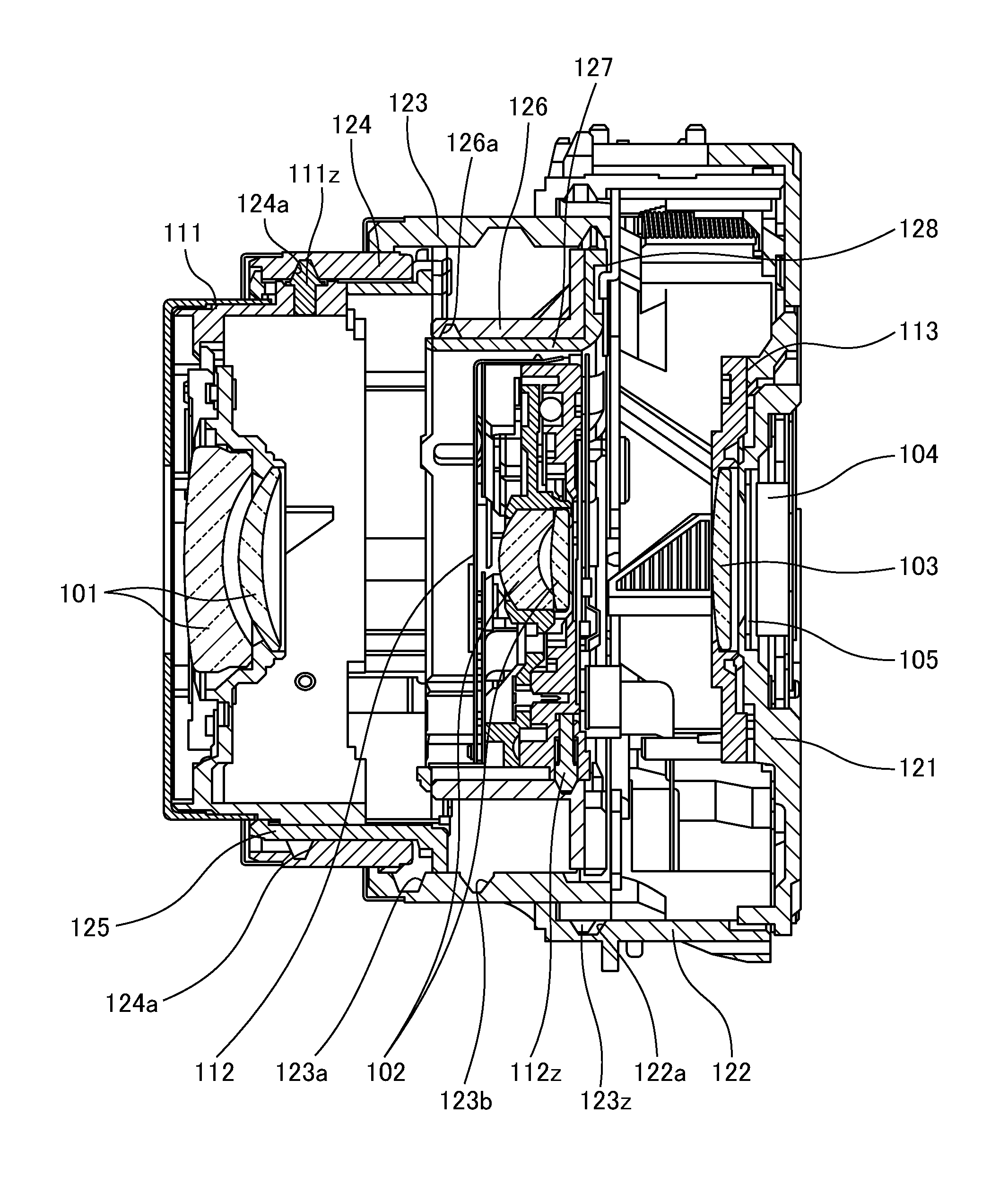
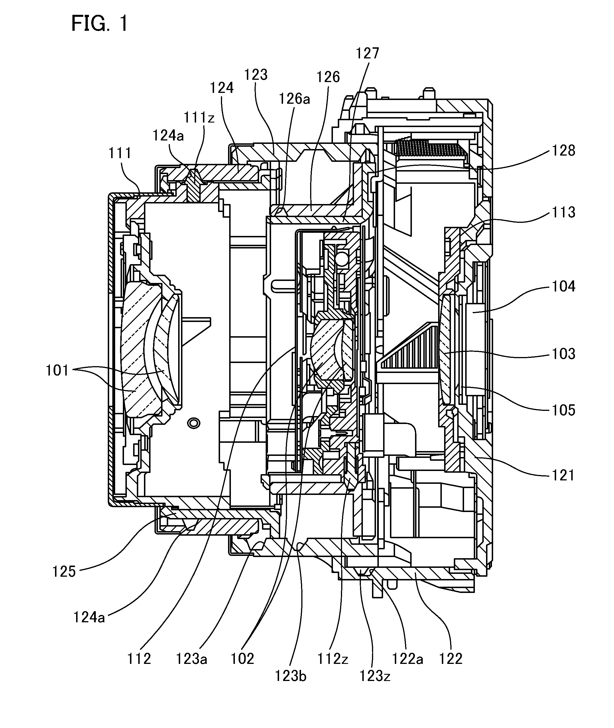
[0024]Hereinafter, as an embodiment according to the imaging apparatus of the present invention, a description will be given of an exemplary configuration of an apparatus provided with a three-stage retractable lens barrel. FIG. 1 is a central sectional view illustrating the lens barrel that is cut along the optical axis. A schematic description will be given of the configuration of the lens barrel with reference to FIG. 1. An imaging optical system includes a first lens group (hereinafter referred to as “first group”) 101, a second lens group (hereinafter referred to as “second group”) 102, and a third lens group (hereinafter referred to as “third group”) 103. Each lens group is typically configured by a plurality of optical members, and the third group 103 (a single lens in the present example) precedes an imaging element 104. The imaging element 104 converts a subject image formed through the lens groups into an electrical signal, and outputs an imaging signal to a signal process...


PUM


Abstract

For a lens barrel that restricts the rectilinear of a lens group using a restricting portion such as a rectilinear key, the light-shielding property for external light, the degree of freedom of design relating to the arrangement of the interlocking section for a cam ring, as well as a change in the relative distance between a front group and a rear group are increased. A lens barrel has a first group (front group) 101 and a second group (rear group) 102 that are movable in the optical axis direction. The first group cam ring 124 is cam-engaged with and held by the holding member (the first group barrel 111) of the first group 101, and the second group cam ring 126 is cam-engaged with and held by the holding member (the second group barrel 112) of the second group 102. The moving cam ring 123 guides the first group cam ring 124 and the second group cam ring 126, and the fixed tube 122 is cam-engaged with the moving cam ring 123 to thereby rotatably support it. The front group and the rear group are cam-engaged with and held by different cam rings. The front group and the rear group are held and guided by the moving cam ring 123.

Description

BACKGROUND OF THE INVENTION[0001]1. Field of the Invention[0002]The present invention relates to a technique for improving the light-shielding property, the degree of freedom of design, and the operation accuracy of a lens barrel for use in an imaging apparatus such as a digital camera.[0003]Furthermore, the present invention relates to a technique for increasing the movement stroke of a lens group in a retracted state, for a lens barrel for use in an imaging apparatus such as a digital camera, while keeping the lens barrel thin.[0004]2. Description of the Related Art[0005]For a lens barrel, a configuration in which a front group and a rear group of a lens group barrel are cam-engaged and held so as to restrict the rotation of the front group and the rear group using a guide member having a key for rectilinear restriction is known. Japanese Patent Laid-Open No. 2007-219304 discloses a shooting barrel in which the outer periphery portion, which is positioned outside a rectilinear key...

Claims


Application Information

Patent Timeline
Patent Type & Authority Patents(United States)
IPC IPC(8): G02B7/02
CPCG02B7/102G03B11/04G03B17/02G03B17/04G02B7/02
Inventor IIDA, SEIJI
Owner CANON KK
Why Eureka
Try Eureka