Phase detector, phase detecting method, and clock-and-data recovery device
a phase detector and detection method technology, applied in the direction of digital transmission, transmission monitoring, line-transmission details, etc., can solve problems such as phase detection error, and achieve the effect of accurate sampled data
- Summary
- Abstract
- Description
- Claims
- Application Information
AI Technical Summary
Benefits of technology
Problems solved by technology
Method used
Image
Examples
first embodiment
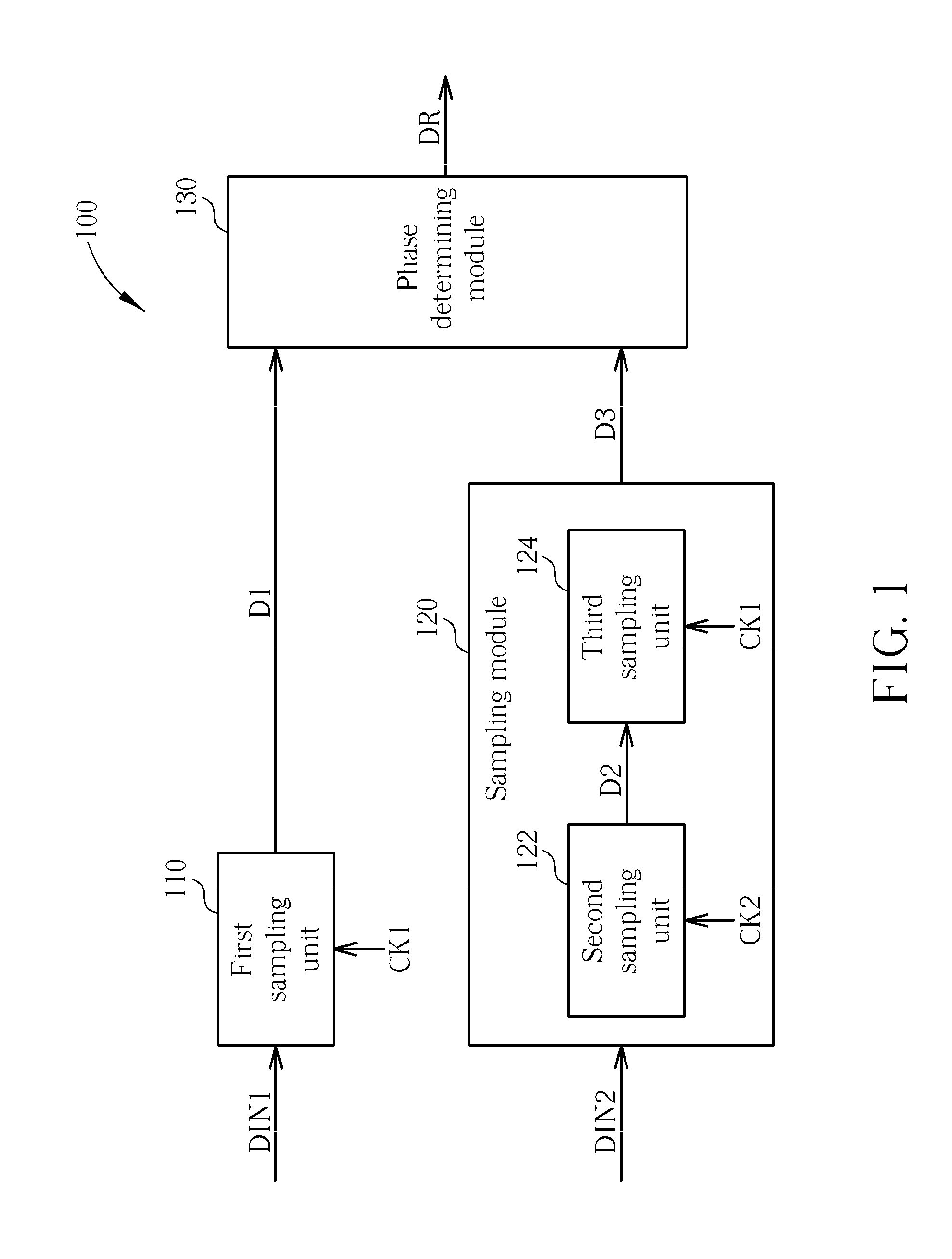
[0026]Please refer to FIG. 1. FIG. 1 is a diagram of a phase detector according to the present disclosure. As shown in FIG. 1, the phase detector 100 may include, but is not limited to, a first sampling unit 110, a sampling module 120, and a phase determining module 130. The first sampling unit 110 is arranged for sampling a first data input signal DIN1 to generate a first data signal D1 according to a first clock signal CK1. The sampling module 120 may include a second sampling unit 122 and a third sampling unit 124, wherein the second sampling unit 122 is arranged for sampling a second data input signal DIN2 to generate a second data signal D2 according to a second clock signal CK2, and the third sampling unit 124 is coupled to the second sampling unit 122 and is arranged for sampling the second data signal D2 to generate a third data signal D3 according to the first clock signal CK1. The phase determining module 130 is coupled to the first sampling unit 110 and the third sampling...
second embodiment
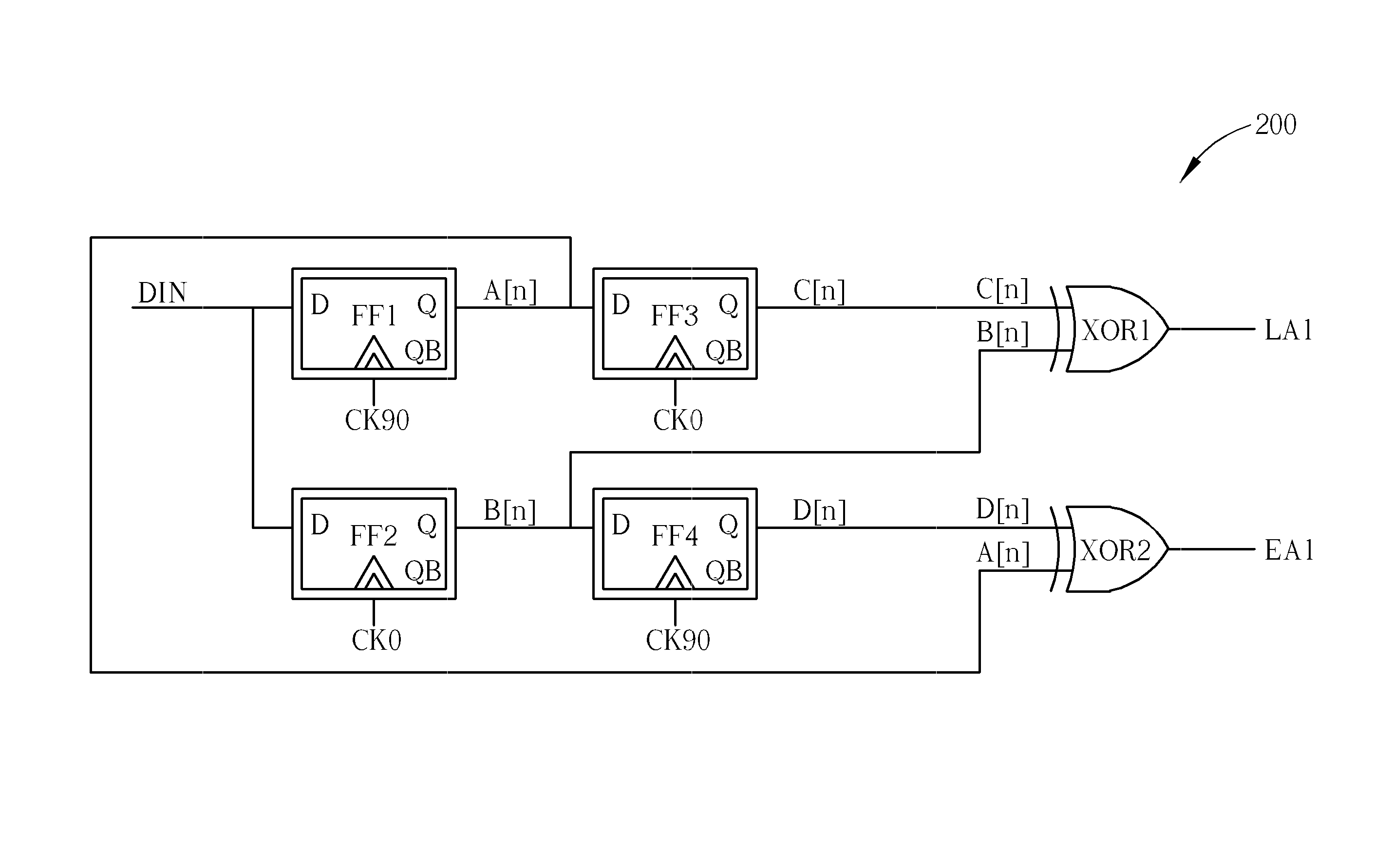
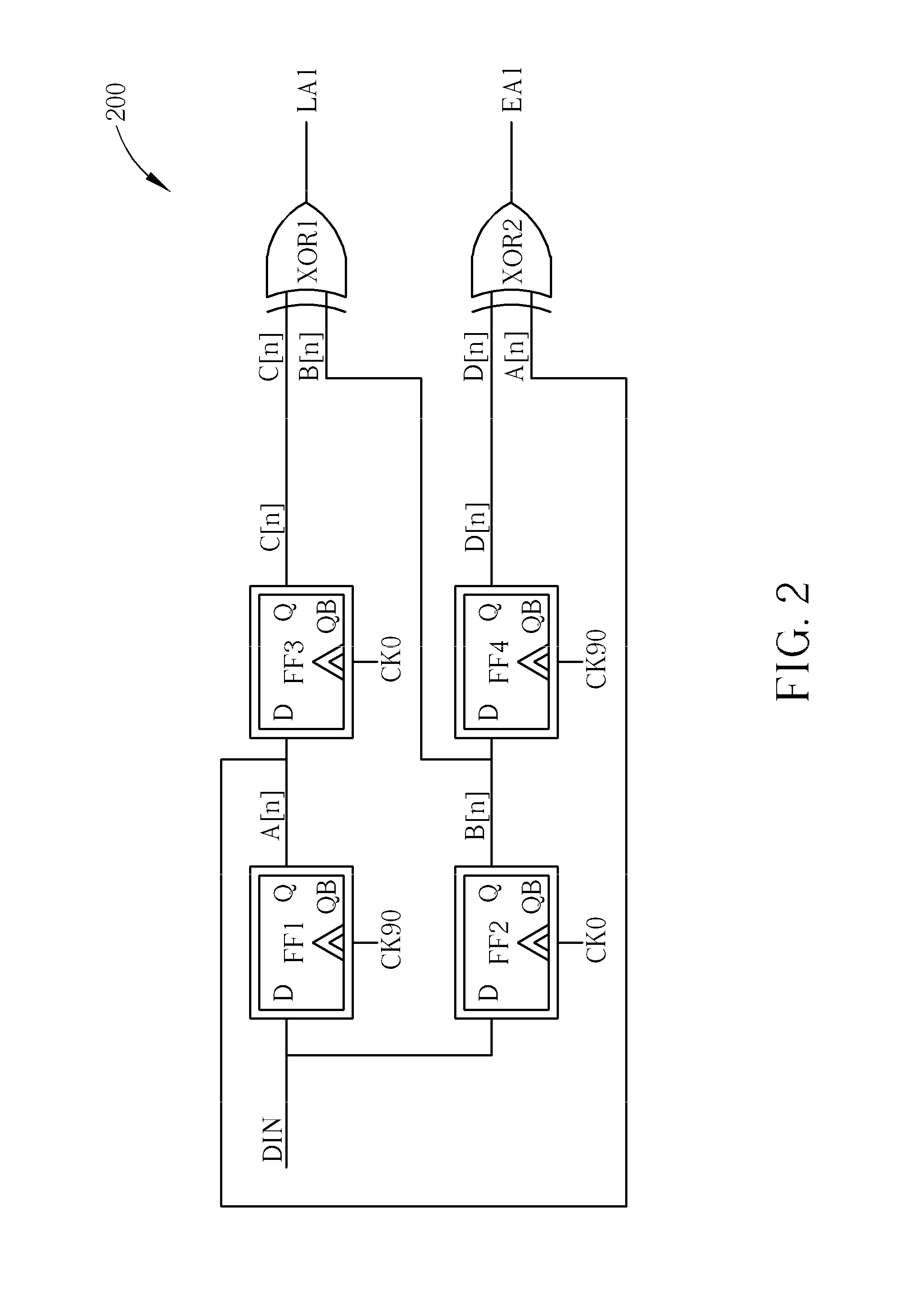
[0027]Please refer to FIG. 2, FIG. 3, together with FIG. 4. FIG. 2 is a diagram of a phase detector 200 according to the present disclosure; FIG. 3 is a diagram illustrating how the phase detector 200 shown in FIG. 2 samples the data input signal; and FIG. 4 is a signal timing diagram of the phase detector 200 shown in FIG. 2. In this embodiment, the first data input signal DIN1 and the second data input signal DIN2 are implemented by using the same data input signal DIN. As shown in FIG. 2, the phase detector 200 may include, but is not limited to, a first flip-flop FF1, a second flip-flop FF2, a third flip-flop FF3, a fourth flip-flop FF4, a first exclusive OR gate XOR1, and a second exclusive OR gate XOR2. Please note that: in this embodiment, there is a phase shift of 90 degrees existed between the clock signal CK90 and the clock signal CK0.
[0028]Please refer to FIG. 1 together with FIG. 2. During a stage of determining an advance signal EA1, the first flip-flop FF1 is acted as ...
third embodiment
[0033]Please refer to FIG. 5, FIG. 6, together with FIG. 7. FIG. 5 is a diagram of a phase detector 500 according to the present disclosure; FIG. 6 is a diagram illustrating how the phase detector 500 shown in FIG. 5 samples the data input signal; and FIG. 7 is a signal timing diagram of the phase detector 500 shown in FIG. 5. The architecture of the phase detector 500 shown in FIG. 5 is similar to that of the phase detector 200 shown in FIG. 2, and the difference between them is that: there is a phase shift of 45 degrees existed between the clock signal CK0, the clock signal CK45, the clock signal CK90, and the clock signal CK135. As shown in FIG. 5, the phase detector 500 may include, but is not limited to, a first flip-flop FF1, a second flip-flop FF2, a third flip-flop FF3, a fourth flip-flop FF4, a fifth flip-flop FF5, a sixth flip-flop FF6, a seventh flip-flop FF7, an eighth flip-flop FF8, a first exclusive OR gate XOR1, a second exclusive OR gate XOR2, a third exclusive OR ga...
PUM
 Abstract
Description
Claims
Application Information
 - R&D
- Intellectual Property
- Life Sciences
- Materials
- Tech Scout
- Unparalleled Data Quality
- Higher Quality Content
- 60% Fewer Hallucinations
Browse by: Latest US Patents, China's latest patents, Technical Efficacy Thesaurus, Application Domain, Technology Topic, Popular Technical Reports.
© 2025 PatSnap. All rights reserved.Legal|Privacy policy|Modern Slavery Act Transparency Statement|Sitemap|About US| Contact US: help@patsnap.com


