Thermal expansion/surge reduction water tank

a water tank and expansion valve technology, applied in the field of hot water systems, can solve the problems of damage to surrounding structures, insufficient sealing, and inability to meet the needs of use,

Active Publication Date: 2013-09-03
ADVANCED CONSERVATION TECH DISTRIBUTION
View PDF23 Cites 25 Cited by
  • Summary
  • Abstract
  • Description
  • Claims
  • Application Information

AI Technical Summary

Benefits of technology

[0008]A plurality of protuberances are provided and disposed on one side of the bladder facing the second compartment for preventing sealing of the bladder in an area of abutment with the housing inside between the water inlet and the water outlet thereby enabling fluid flow between the water inlet and the water outlet with the bladder abutting the housing inside.
[0009]In this manner, the bladder is prevented from sealing against the housing inside which may restrict the flow of small amounts of water through.

Problems solved by technology

While most water heater systems utilize check valves or pressure-rated vessels for eliminating safety concerns caused by pressure fluctuations, the efficiency issue is still present.
As hereinabove noted, water heaters generally incorporate a pressure relief valve to prevent excessive pressure buildup but unfortunately release of water from these valves results from generally uncontrolled release of water from the water heater which most likely may cause damage to surrounding structure.
In addition, once a pressure relief valve is opened, it may not seal properly again thereby providing a continuous leak.
In addition, when the hot water systems are subject to “water hammer”, which is a pounding noise or vibration developed in the piping system, when non-compressible water flowing through a pipe at a given pressure and velocity is abruptly stopped.
The surging shock wave may oscillate within the piping system until the destructive energy is dissipated.
This action accounts for piping noise and vibration and may cause ruptured piping, leaking connections, and ruptured tanks.
Unfortunately, these tanks tend to accumulate stagnant water which may contribute to health and safety issues of the plumbing system.

Method used


Image

  • Thermal expansion/surge reduction water tank
  • Thermal expansion/surge reduction water tank
  • Thermal expansion/surge reduction water tank

Examples


Embodiment Construction

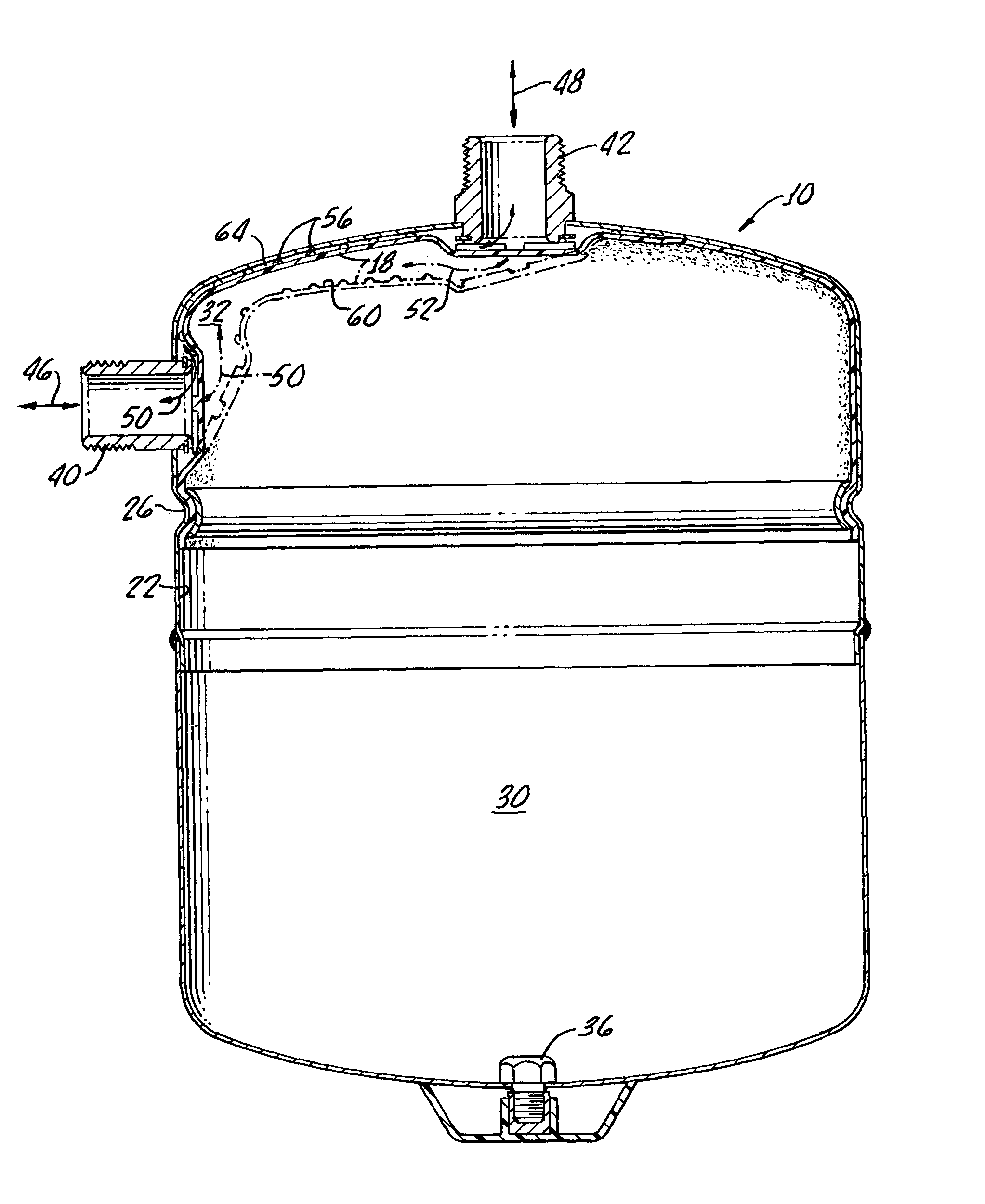
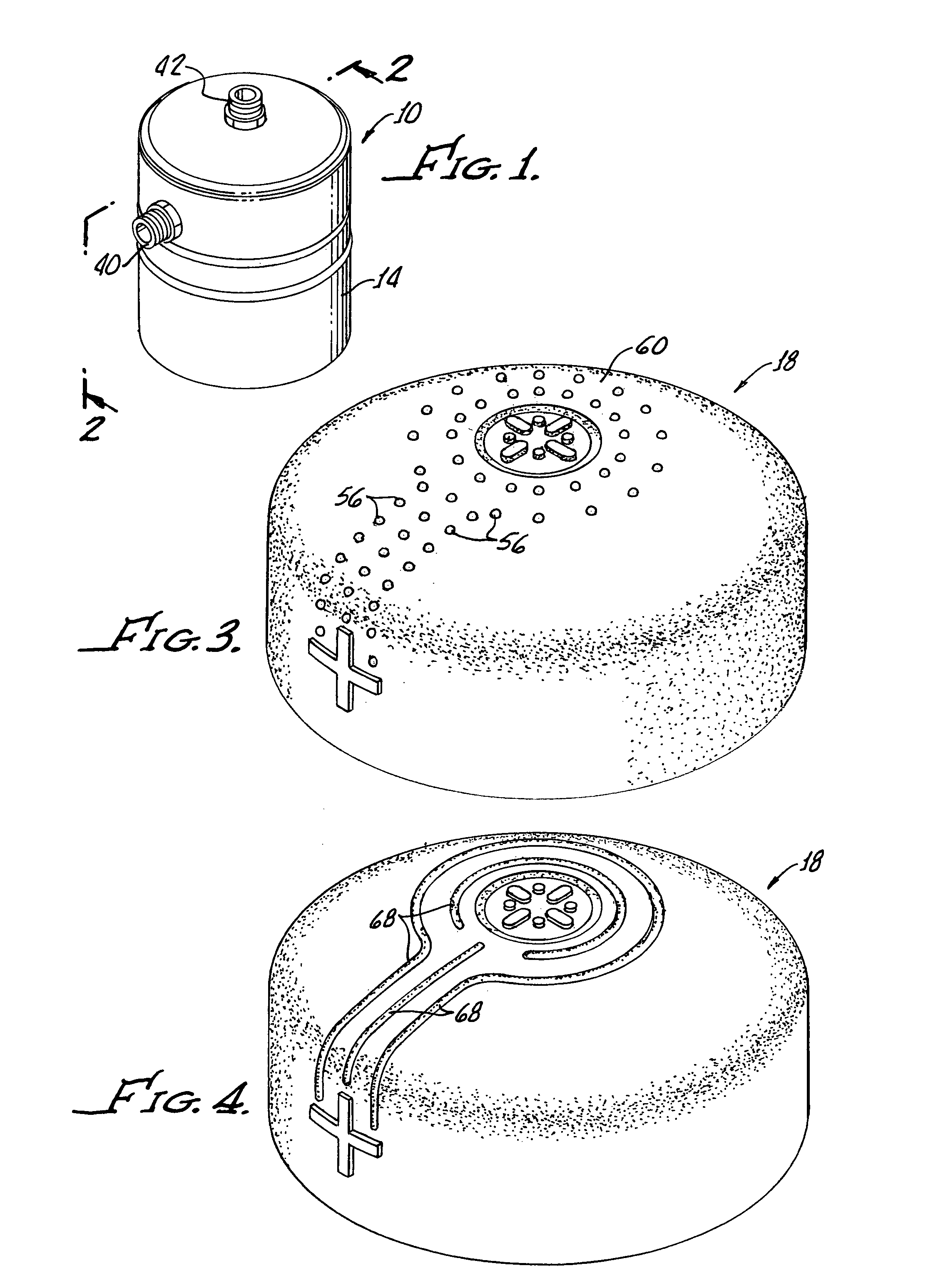
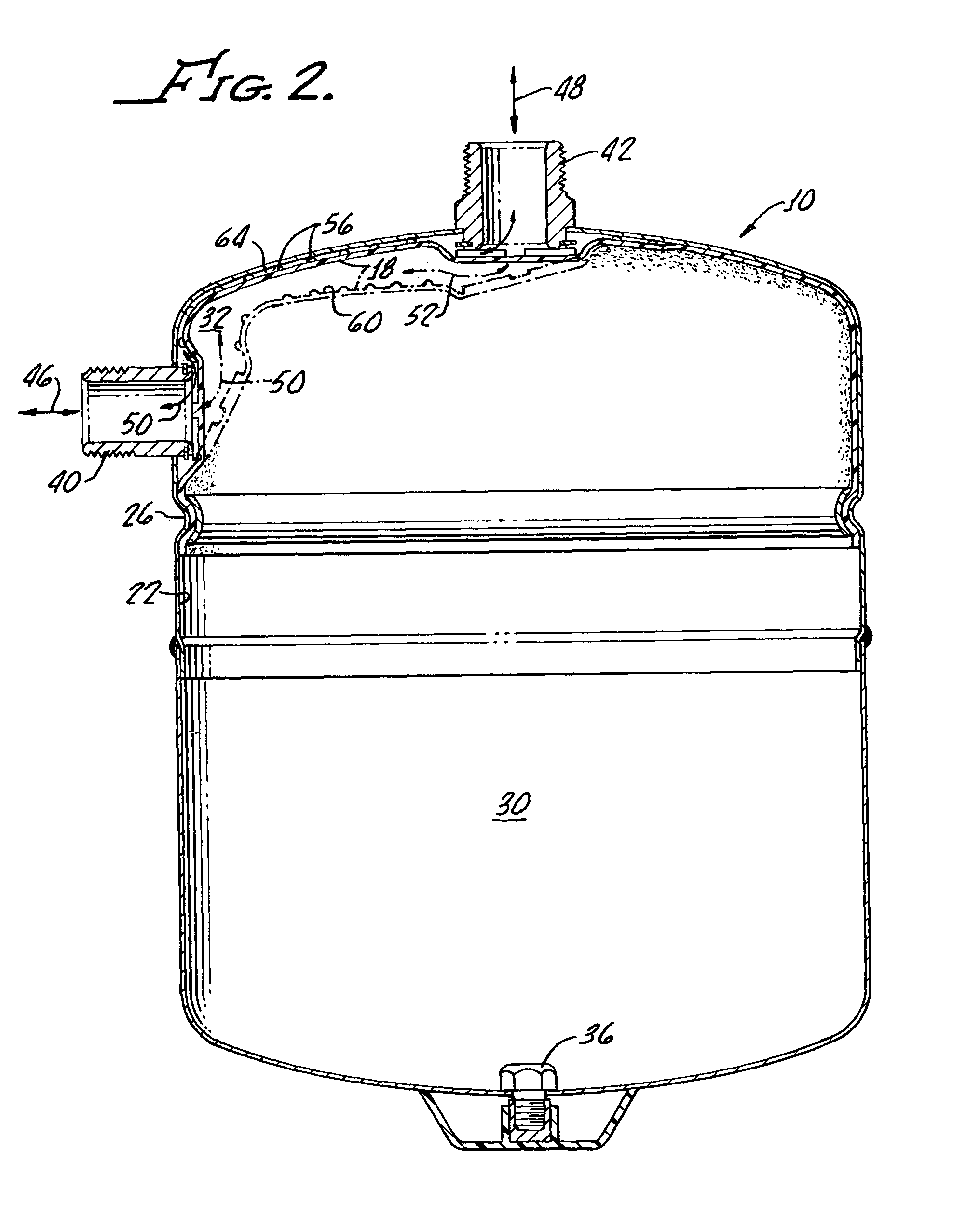
[0017]With reference to FIGS. 1 and 2, there is shown a thermal expansion / surge reduction water tank 10 in accordance with the present invention generally showing a hollow housing 14 having a bladder 18 sealed to a housing inside 22 at a perimeter 26 thereby forming a first compartment 30 and a second compartment 32 within the hollow housing 14.

[0018]A compressed air inlet 36 is provided in communication with a first compartment 30 for inflating the bladder 18 into an abutting relationship with the housing inside as shown in solid line in FIG. 2. Fittings 40, 42 provide for water inlet and outlet from the tank 10 with the water flow therebetween being indicated by arrows 46, 48, 50, 52.

[0019]Because the fittings 40, 42 are disposed at an acute angle, for example, 90 degrees as shown in FIG. 2, the flow of water through the second compartment will be non-laminar thus causing a roiling or churning action within the second compartment with such turbulence effecting self-cleaning of the...


PUM


Abstract

A thermal expansion / surge reduction water tank includes a hollow housing with a bladder sealed to an inside of the housing forming two compartments therein. A compressed air inlet in communication with a first of the compartments is provided for expanding the first compartment by focusing the bladder into an abutting relationship with the housing inside. A water inlet and a water outlet in communication with a second of the compartments is provided and disposed for causing non-laminar flow of water through the second compartment for both expanding the second compartment by forcing said bladder into the first compartment and flushing the second compartment to effect self-cleaning thereof. A plurality of protuberances disposed on a side of said bladder facing the second compartment are provided for preventing sealing of the bladder in an area of abutment with the housing inside between the water inlet and outlet thereby enabling fluid flow between the water inlet and outlet with said bladder abutting the housing inside.

Description

[0001]The present invention is generally related to hot water systems and is more particularly directed to thermal expansion / surge reduction water tanks utilizing a compressible volume of air to prevent or relieve the buildup of pressure.[0002]Temperature variations within closed water systems occur in both commercial and residential buildings. While most water heater systems utilize check valves or pressure-rated vessels for eliminating safety concerns caused by pressure fluctuations, the efficiency issue is still present. As hereinabove noted, water heaters generally incorporate a pressure relief valve to prevent excessive pressure buildup but unfortunately release of water from these valves results from generally uncontrolled release of water from the water heater which most likely may cause damage to surrounding structure. In addition, once a pressure relief valve is opened, it may not seal properly again thereby providing a continuous leak.[0003]In addition, when the hot water ...

Claims


Application Information

Patent Timeline
Patent Type & Authority Patents(United States)
IPC IPC(8): F17C1/00
CPCF16J3/02F16J12/00F24D3/1008F24D3/1016F24D3/1041
Inventor ACKER, LARRY K.
Owner ADVANCED CONSERVATION TECH DISTRIBUTION
Why Eureka
Try Eureka