Image processing apparatus and image processing method for removing residual image

a residual image and image processing technology, applied in the field of image processing apparatus and image processing method for removing residual images from images, can solve the problems of increasing the cost of hardware resources, the inability to contain all the correction coefficients in the x-ray imaging device, and the difficulty of manufacturing all the sensing elements with perfectly uniform properties, so as to achieve the effect of avoiding time and cos

Active Publication Date: 2013-09-03
FUJIFILM CORP
View PDF34 Cites 8 Cited by
  • Summary
  • Abstract
  • Description
  • Claims
  • Application Information

AI Technical Summary

Benefits of technology

[0014]An object of the present invention is to provide an image processing apparatus and an image processing method for removing noise from an image with the least expenditure of cost and time.
[0026]According to the present invention, the residual image is removed from the image without time and cost by the image correction.

Problems solved by technology

Since the size of the FPD is extremely large compared to imaging sensors such as CCD and CMOS used for digital cameras, it is difficult to manufacture all the sensing elements with perfectly uniform properties.
There are enormous numbers of correction coefficients corresponding to all possible combinations of the parameters, and it is just impractical to contain all the correction coefficients in the X-ray imaging device.
First, cost for hardware resources increase due to an enormous memory capacities to store all the correction coefficients.
Such measurement or calculation requires massive cost and time.
Thus, it is impractical to contain all the correction coefficients for just one parameter as is the case with multiple parameters.

Method used


Image

  • Image processing apparatus and image processing method for removing residual image
  • Image processing apparatus and image processing method for removing residual image
  • Image processing apparatus and image processing method for removing residual image

Examples


first embodiment

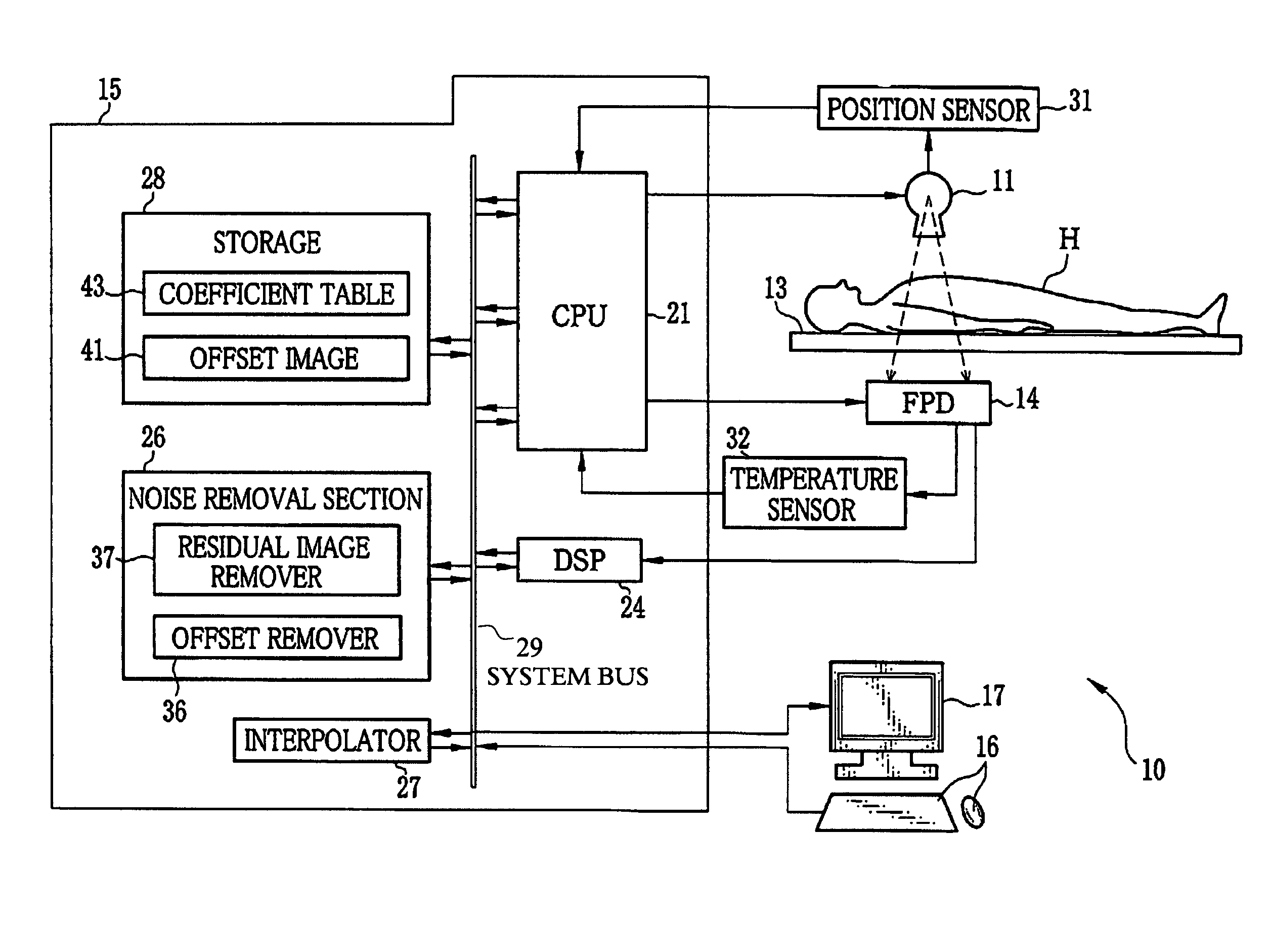
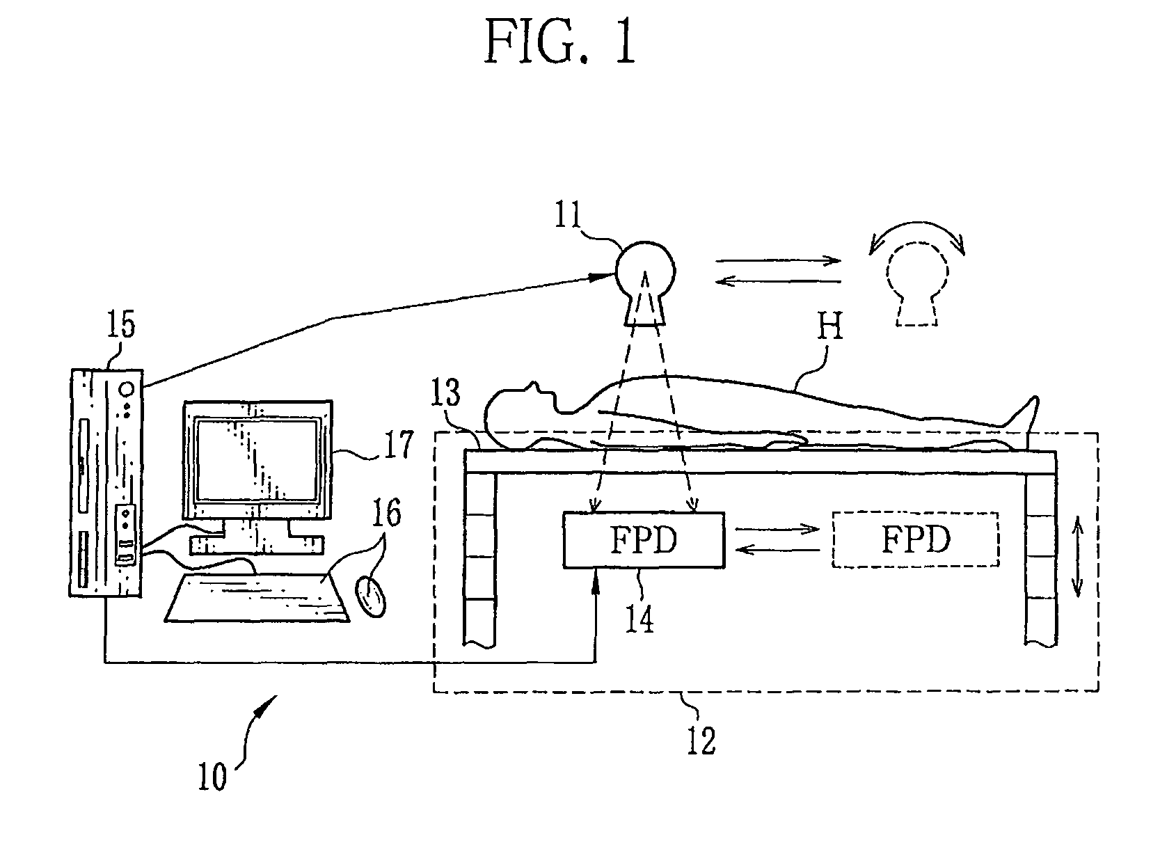
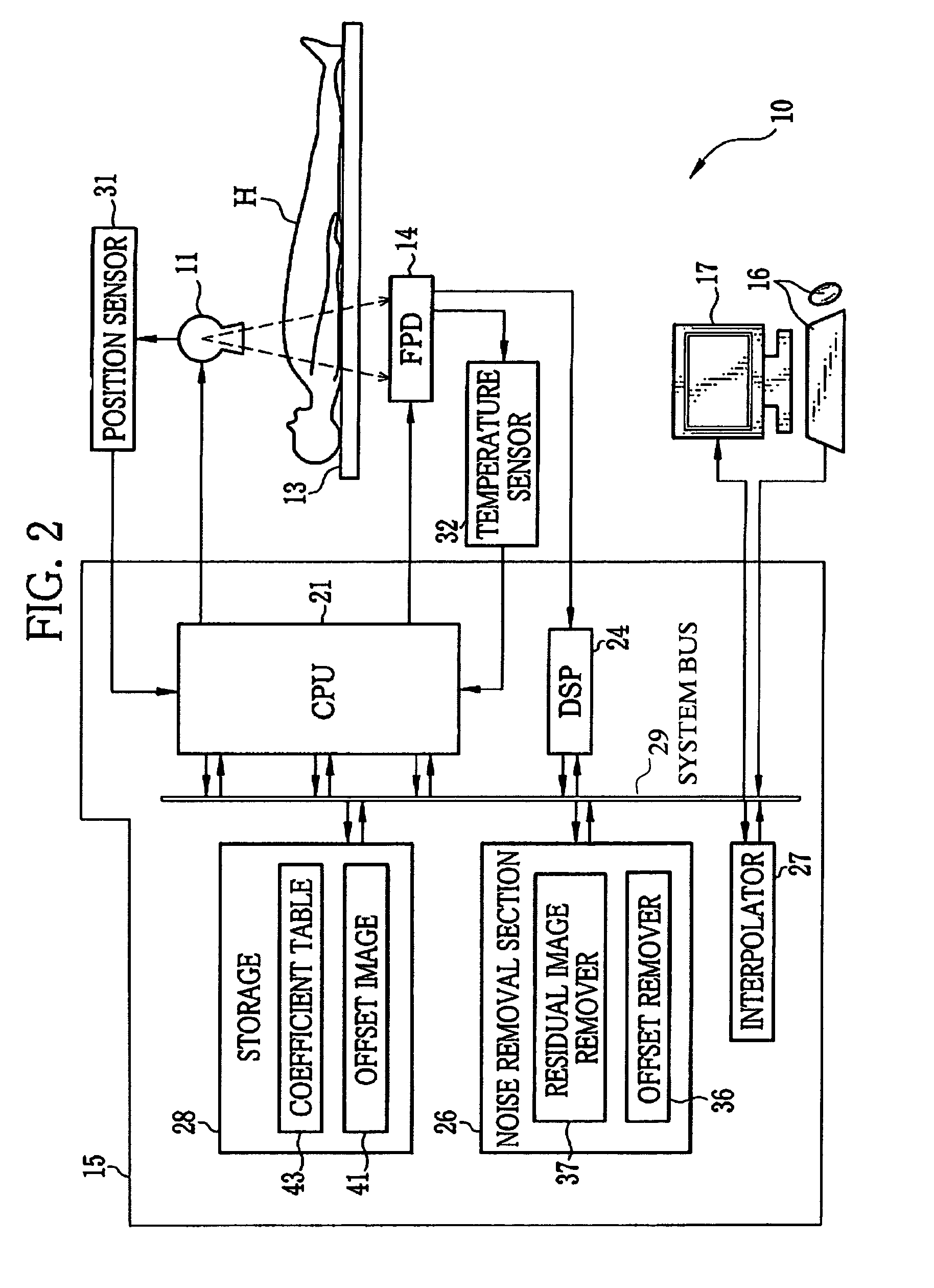
[0045]As shown in FIG. 1, an X-ray imaging system or radiographic imaging system 10 is a system for taking digital radiographic images of a patient (subject) H by irradiating the patient with X-rays. The X-ray imaging system 10 is composed of an X-ray source 11, an X-ray imaging apparatus 12, an image processing apparatus 15 and the like. The X-ray imaging apparatus 12 is composed of an X-ray table 13, a FPD 14 and the like.

[0046]The X-ray source 11 is an X-ray tube that produces X-ray by accelerating and impacting electrons on a target, such as tungsten or molybdenum, from a cathode filament (not shown). Adjusting the X-ray tube current and the X-ray tube voltage supplied to the cathode changes the dose and the radiation quality of X-rays irradiated from the X-ray source 11. The dose and the radiation quality of X-rays are changed as necessary depending on the thickness of the patient H and a body site thereof.

[0047]The X-ray source 11 is mounted on a ceiling (not shown) of an X-ra...

second embodiment

[0093]The X-ray imaging system 10 takes images of various patients (subjects) H in corresponding imaging conditions. It is rare that the parameters of the exposure coincide with parameters (storage time and FPD temperature) previously stored in the coefficient table 43. In many cases, the interpolator 27 calculates the coefficient by interpolation. A relatively high machine power is required for the image processing apparatus 15 in a case where a coefficient is calculated for every exposure. In this embodiment, an example of the X-ray imaging system 10 that requires less machine power is described. A component similar to that in FIG. 2 is designated by the same numeral shown in FIG. 2, and a description thereof is omitted.

[0094]Unlike the first embodiment, in an X-ray imaging system 71 shown in FIG. 15, a threshold value 72 is previously stored in the storage 28. For the second and subsequent images taken after the startup of the X-ray imaging system 71, the threshold value 72 is co...


PUM


Abstract

An X-ray imaging system is provided with an FPD and an image processing apparatus. The image processing apparatus is provided with a CPU, a coefficient table, an interpolator and a residual image remover. The CPU acquires an image taken with the FPD. A plurality of coefficients each corresponding to a parameter that changes an attenuation curve are previously stored in the coefficient table. The attenuation curve represents time-varying attenuation of a residual image of the previous image. In a case where the coefficient corresponding to a parameter of the present exposure is not contained in the coefficient table, an appropriate coefficient is calculated by interpolation based on the coefficients contained in the coefficient table. The residual image remover calculates the residual image based on the stored coefficient or the calculated coefficient and a time lapse between the previous and subsequent exposures, and removes the residual image from the present image.

Description

CROSS-REFERENCE TO RELATED APPLICATIONS[0001]The present application claims priority from Japanese Patent Application No. 2008-310466, filed Dec. 5, 2008, the contents of which are herein incorporated by reference in their entirety.FIELD OF THE INVENTION[0002]The present invention relates to an image processing apparatus and an image processing method for removing a residual image from an image.BACKGROUND OF THE INVENTION[0003]X-ray imaging systems are widely used in the medical field. The X-ray imaging system takes images of an internal structure a patient (subject) using X-ray. Absorption and scattering rates of X-rays vary depending on the organs and the thickness of the body of a patient. X-ray attenuates while it passes through the patient, reflecting the internal structure of the patient. In a conventional X-ray imaging system, a patient is placed between an X-ray source and a film to which a photosensitive agent is applied, and X-ray which passed through the patient is record...

Claims


Application Information

Patent Timeline
Patent Type & Authority Patents(United States)
IPC IPC(8): G01D18/00G06K9/36
CPCG06T5/50G06T11/00G06T11/005G06T2207/10116
Inventor TSUJI, TETSUYA
Owner FUJIFILM CORP
Why Eureka
Try Eureka