
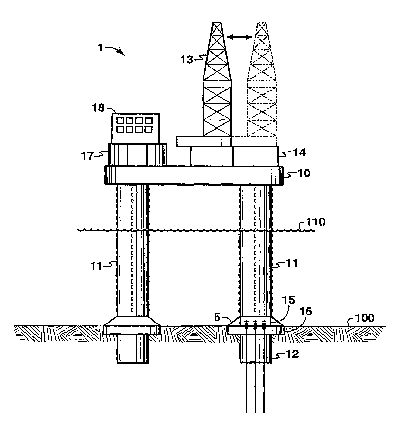
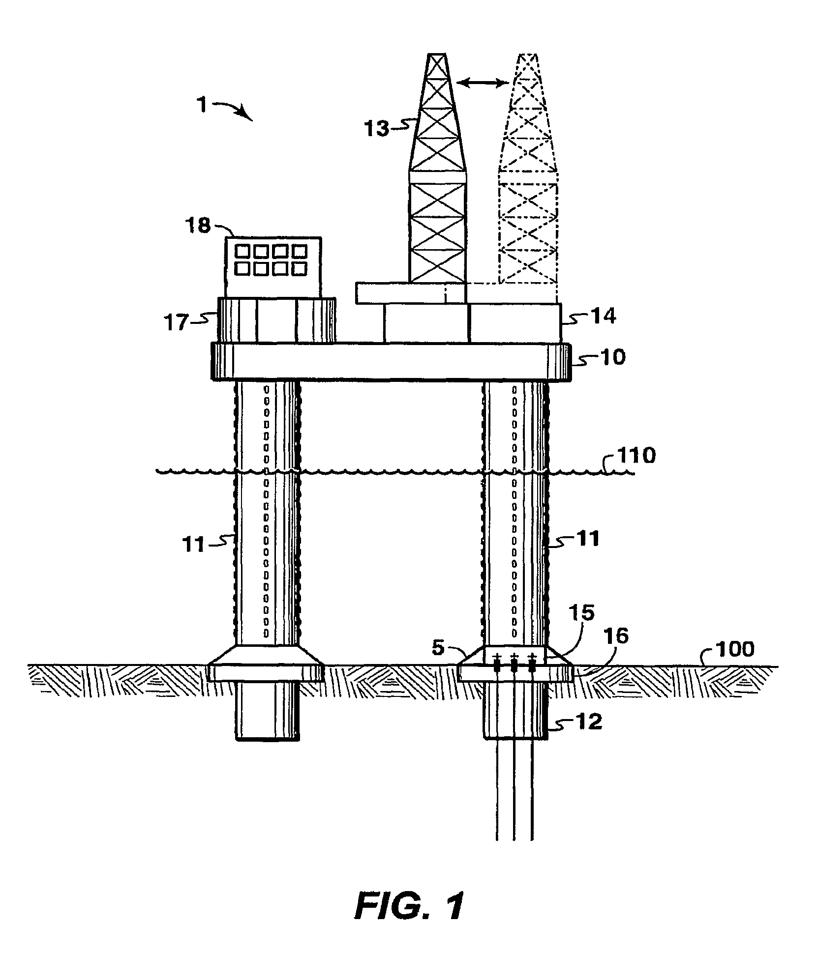
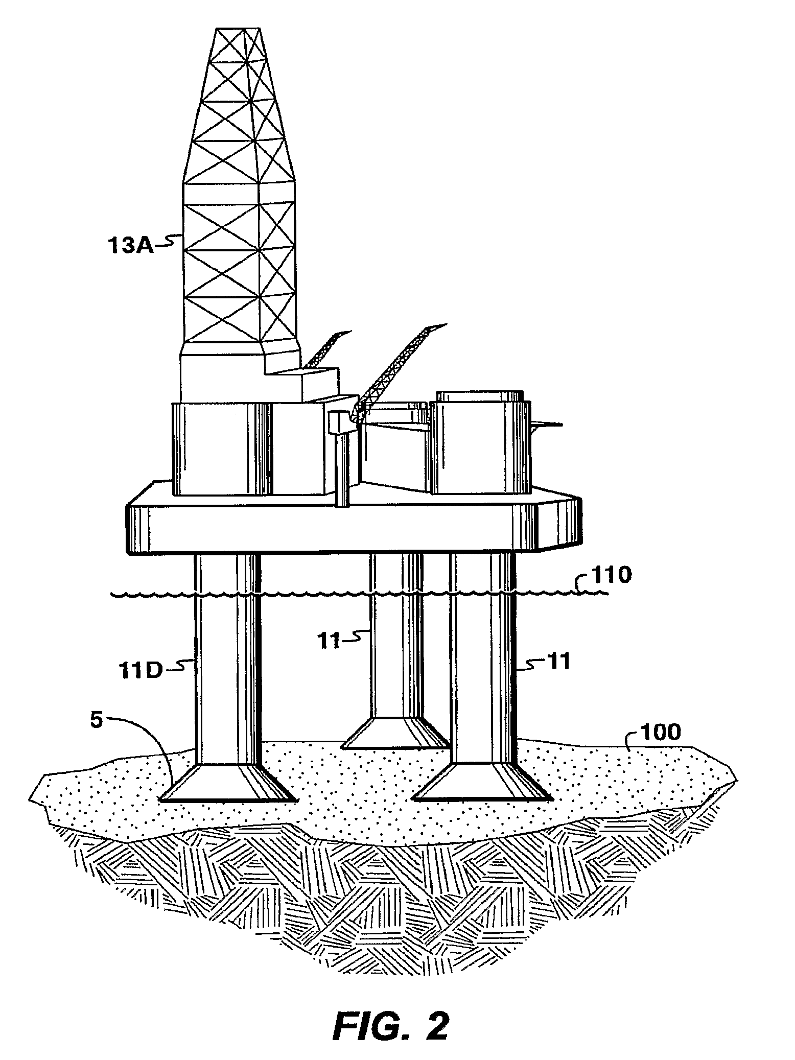
Mobile, year-round arctic drilling system

a drilling system and arctic technology, applied in special-purpose vessels, floating buildings, transportation and packaging, etc., can solve the problems of ice impingement, large pressure forces, and the use of standard offshore drilling systems

Active Publication Date: 2013-09-03
EXXONMOBIL UPSTREAM RES CO
View PDF46 Cites 3 Cited by
  • Summary
  • Abstract
  • Description
  • Claims
  • Application Information

AI Technical Summary

Benefits of technology

The patent text describes a method of re-installing an offshore drilling system in a water body. The mobile drilling system has a hull and two legs, each with a closed structure including an outer plate and an inner plate forming an annulus. A bonding agent is placed in the annulus. The method includes transporting the system to a drilling location, lowering the legs to the seabed, elevating the hull above the surface, and penetrating the remaining legs' foundation into the seabed. The drilling rig is then positioned over the drilling location. The foundation protects the wellheads and one of the legs is lowered into the first foundation using a guide system. The technical effect of the invention is to provide an efficient and cost-effective method for re-installing offshore drilling systems.

Problems solved by technology

However, even the sub-arctic environment presents problems for the use of standard offshore drilling systems.
Thus, the structure of a typical offshore drilling structure would not able to withstand the significantly higher forces in a sub-arctic environment.
Ice impingement can also create large pressure forces in small, local areas of any drilling equipment structure.
For a typical offshore drilling system, these high local forces would damage unprotected frame brace elements since these elements are typical offshore structures designed solely to resist wind, waves and current.
However, most of these structures are configured as permanent (non-mobile), production / drilling / quarters (PDQ) platforms.
However, this configuration is only designed for exploration drilling with no provision for re-deployment over an active well site.
Further, the single-column design may not be structurally sound for seismically-active locations.
Existing mobile drilling systems for non-arctic conditions, such as the conventional jack-up system, cannot operate in areas where the structure may come into contact with ice floes.
Neither of these existing designs is capable of resisting local and global loading due to sub-arctic ice.
The open-lattice leg design is not suitable to resist the local ice forces as individual members of the lattice structure would be bent or crushed by the local ice forces.
However, current designs are not suitable to resist the high local ice loads as the legs are primarily designed to resist much smaller wave loading.
Neither of the above designs is capable of resisting the global ice loads typical of sub-arctic regions.
Preferably, the relocation time may be relatively short and require no significant offshore logistics support (i.e., nothing more than a few towing vessels).

Method used


Image

  • Mobile, year-round arctic drilling system
  • Mobile, year-round arctic drilling system
  • Mobile, year-round arctic drilling system

Examples


Embodiment Construction

[0031]In the following detailed description section, the specific embodiments of the present invention are described in connection with preferred embodiments. However, to the extent that the following description is specific to a particular embodiment or a particular use of the present invention, this is intended to be for exemplary purposes only and simply provides a description of the exemplary embodiments. Accordingly, the invention is not limited to the specific embodiments described below, but rather, it includes all alternatives, modifications, and equivalents falling within the true spirit and scope of the appended claims.

[0032]It may be economically advantageous to develop offshore oil and gas reservoirs by locating well centers at de-centralized locations. Having several drilling centers may allow better reservoir recovery, for example. Also, if one section of a reservoir is discovered to have lower than expected recovery, a smaller, de-centralized well center can be decomm...


PUM


Abstract

A mobile, year-round drilling system (MYADS) for drilling offshore wells and / or performing other offshore activities at multiple, successive locations in an arctic or sub-arctic environment is provided. The present invention combines the ability to move to different locations and the strength to resist ice loading when on location and when ice-covering is present in the arctic or sub-arctic environment. The MYADS applies a multiple leg “jack-up” concept in which supporting legs are lowered through a hull to touch down on the seabed and elevate the hull out of the water.

Description

REFERENCE TO PRIORITY APPLICATION[0001]This application is the National Stage entry under 35 U.S.C. 371 of PCT / US2007 / 003903 that published as WO 2007 / 126477 and was filed on Feb. 13, 2007 and claims the benefit of U.S. Provisional Application 60 / 787,602, filed 30 Mar. 2006.BACKGROUND OF THE INVENTION[0002]This section is intended to introduce various aspects of the art, which may be associated with exemplary embodiments of the present invention. This discussion is believed to assist in providing a framework to facilitate a better understanding of particular aspects of the present invention. Accordingly, it should be understood that this section should be read in this light, and not necessarily as admissions of prior art.[0003]The present invention relates to a mobile, year-round arctic drilling system, also referred to herein by the acronym “MYADS.” It is a drilling system for drilling offshore wells and / or performing other offshore activities at multiple, successive locations in a...

Claims


Application Information

Patent Timeline
Patent Type & Authority Patents(United States)
IPC IPC(8): E02D5/74E02B17/02E02D5/54
CPCE02B17/0021E02B17/021E02B17/0017E02B2017/0039E02B2017/0043E02B2017/0056E02B2017/0078E02B2017/0095E02B2017/0052
Inventor BRINKMANN, CARL RHYSDAVENPORT, GEORGE F.
Owner EXXONMOBIL UPSTREAM RES CO
Learn More