Directional cased hole side track method applying rotary closed loop system and casing mill

a rotary closed loop and casing mill technology, applied in the direction of directional drilling, drilling pipes, drilling/well accessories, etc., can solve the problems of increasing rig time, affecting and the tri-cone bit is not suited for cutting through the metal wall of the casing, so as to improve the control and enhance the operation of the bha.

Inactive Publication Date: 2005-07-14
BAKER HUGHES INC
View PDF13 Cites 95 Cited by
  • Summary
  • Abstract
  • Description
  • Claims
  • Application Information

AI Technical Summary

Benefits of technology

[0010] Tools and equipment such as flex subs and stabilizers can be used to enhance the operation of the BHA. For instance, a flex sub provided adjacent and uphole of the steering unit can be used to allow the steering unit to deflect the drill bit orientation relative to the wellbore. Also, one or more active or fixed-blade stabilizers provided adjacent the steering unit and uphole of the flex sub can be used to center the mill during operation. Additionally, on-board sensors and processors can be used to improve control and operation of the BHA. For example, the BHA preferably includes navigation devices to provide information about parameters that may be utilized downhole or at the surface to control the azimuthal orientation of the BHA drilling direction and sensors for measuring drilling motor parameters such as the fluid flow rate, pressure drop, torque, and the rotational speed (RPM) of the motor. The BHA may also inclu...

Problems solved by technology

As is known, a conventional bit (e.g., tri-cone bit) is not suited for cutting through the metal wall of a casing.
As is known, rig time is a factor in the cost of constructing a hydrocarbon producing well.
The repeated assembly and disassembly of work string and tools used in conventional sidetracking op...

Method used


Image

  • Directional cased hole side track method applying rotary closed loop system and casing mill
  • Directional cased hole side track method applying rotary closed loop system and casing mill
  • Directional cased hole side track method applying rotary closed loop system and casing mill

Examples


Embodiment Construction

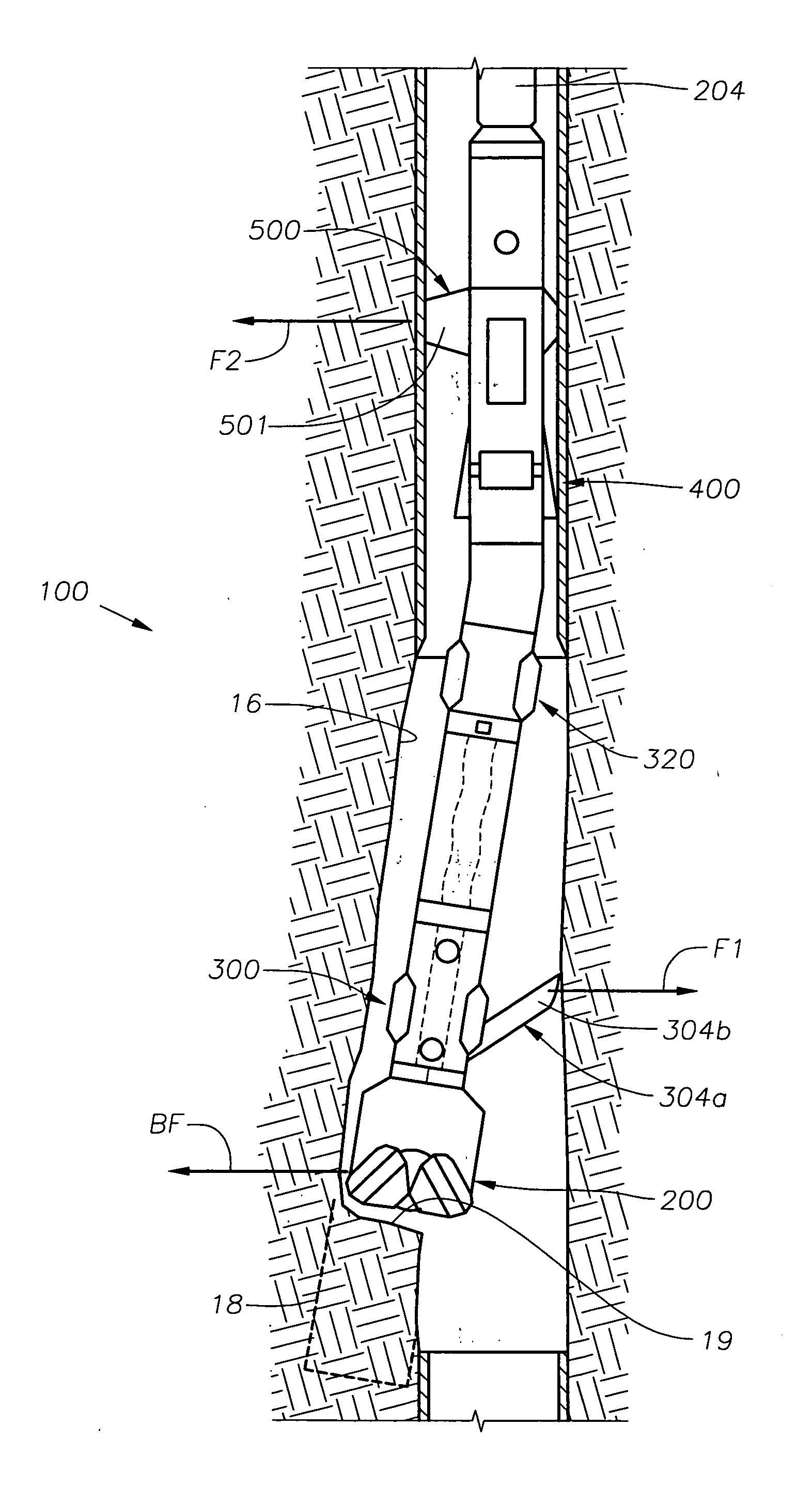
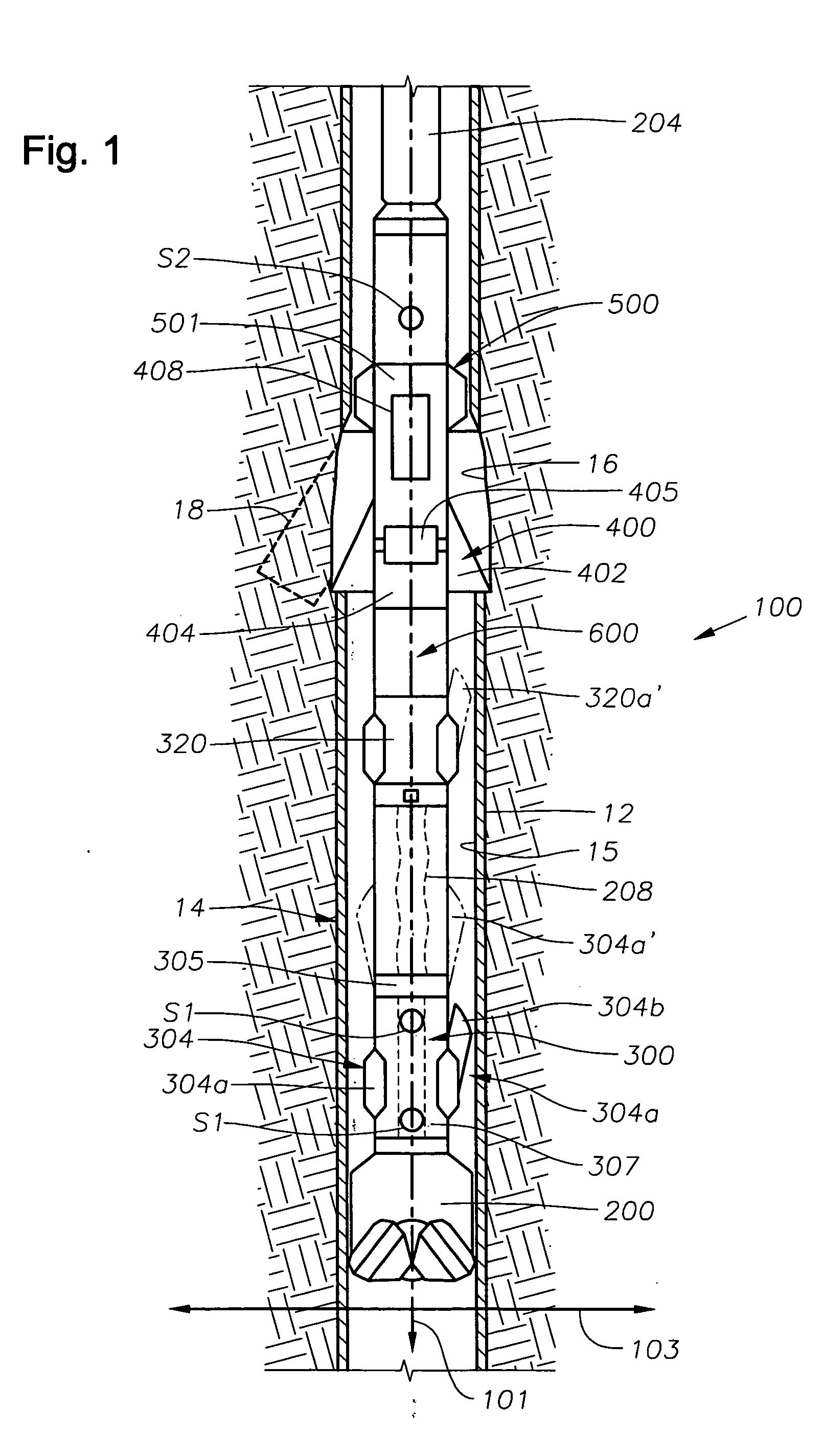
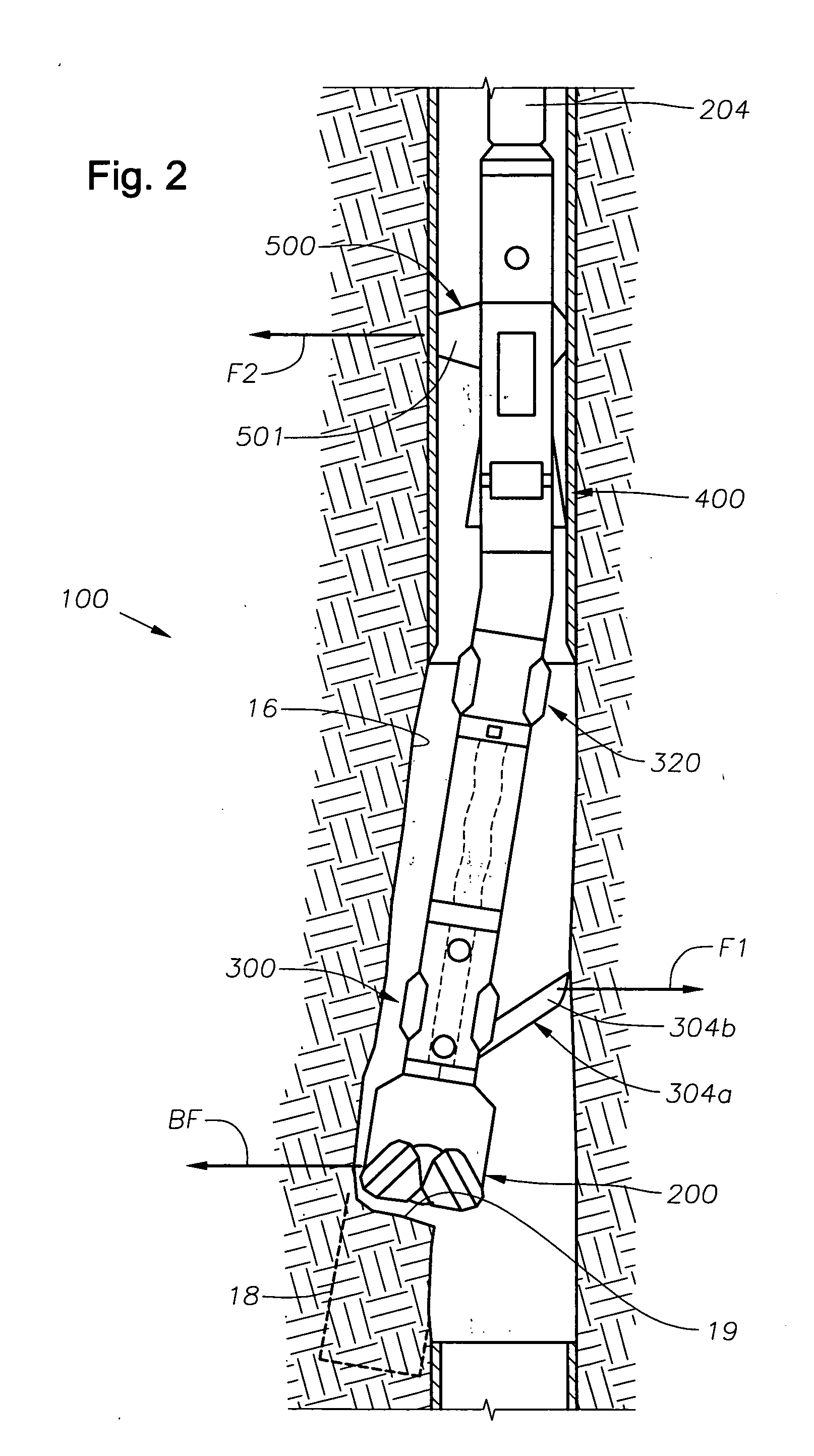
[0017] In one aspect, the present invention provides a bottom hole assembly (BHA) that is adapted to form an opening in a cased section of a main wellbore and drill a sidetrack from the opening. Advantageously, the BHA includes the equipment and tooling to accomplish both tasks during a single trip into the wellbore. An exemplary BHA uses an expandable milling unit to form an opening by removing casing material, cement and other material from a selected cased wellbore section. One or more force application members that extend from the BHA facilitate entry into the opening by urging the BHA into the milled opening. Embodiments adapted to execute sidetracks from a cased wellbore during a single trip are discussed in further detail below.

[0018] Referring now to FIG. 1, there is schematically illustrated a bottom hole assembly (BHA) 100 according to one embodiment of the present invention positioned in a wellbore 14 having a casing 12 therein. The BHA 100 is configured to produce a sid...


PUM


Abstract

A bottomhole assembly (BHA) for single trip sidetracking operations has a mill for forming an open hole section in a cased wellbore and a steering unit for controlling drill bit orientation. During use, the drilling system is assembled at the surface and tripped into the wellbore. The mill is positioned adjacent a kick-off point and operated to form an open hole section. Thereafter, the drill bit is positioned adjacent the open hole section. An exemplary steering unit includes one or more force application members that, when energized, displace the drill bit such that the bit is pointed in a specified direction into the open hole section. The steering unit also includes one or more force application members that facilitate directional drilling through the open hole section. Other suitable steering units can employ devices that alter the BHA centerline geometry.

Description

CROSS-REFERENCE TO RELATED APPLICATIONS [0001] This application takes priority from U.S. Provisional Application Ser. No. 60 / 517,642 filed Nov. 5, 2003, titled “Directional Cased Hole Side Track Method Applying Rotary Closed Loop System and Casing Mill.”BACKGROUND OF THE INVENTION [0002] 1. Field of the Invention [0003] This invention relates, in certain aspects, to systems and methods for forming an open hole section in a cased well and drilling a directional wellbore therefrom during a single trip into a wellbore. [0004] 2. Description of Related Art [0005] For efficient and cost-effective recovery of hydrocarbons from a subterranean formation, it may at times be advantageous to drill a directional or branch wellbore from a location (“kick-off” point) along a cased main wellbore. Conventionally, the drilling of this directional wellbore, sometimes referred to as a sidetracking operation, requires the use of a number of different tools and multiple trips into the wellbore. As is kn...

Claims


Application Information

Patent Timeline
IPC IPC(8): E21B7/04E21B7/06E21B17/10E21B25/16E21B29/06E21B41/00
CPCE21B7/062E21B7/067E21B41/0035E21B29/06E21B17/1014
Inventor BALLANTYNE, RAYOPPELT, JOACHIM
Owner BAKER HUGHES INC
Why Eureka
Try Eureka