Drilling wellbores with optimal physical drill string conditions

a drilling system and drill string technology, applied in the field of oilfield wellbore drilling systems, can solve the problems of difficulty in forming an intuitive understanding of the overall physical condition of the drilling system, conventional systems do not provide information regarding the equipment (e.g., drill string) uphole of the bha, and it is difficult for drillers to provide information regarding the wellbore and adjacent formation uphole, so as to improve the reliability of the various drilling system components, improve the accuracy of directional drilling, and improve the efficiency of directional drilling

Active Publication Date: 2010-06-08
BAKER HUGHES INC
View PDF82 Cites 93 Cited by
  • Summary
  • Abstract
  • Description
  • Claims
  • Application Information

AI Technical Summary

Benefits of technology

[0010]In one aspect, the present invention provides a drilling system including a derrick erected on a floor and a drill string suspended therefrom. A bottomhole assembly (BHA) operatively coupled to an end of the drill string includes a drill bit and known components such as wellbore pressure control devices, thrusters, mud motors, steering units and other known components. The drilling system also can include control units, such as a surface control unit and a downhole control unit, that are programmed to perform any number of selected tasks; e.g., record and process data, control or assist in controlling drilling parameters and / or direction, and monitor drill string and BHA conditions. In one embodiment, the drill string includes sensors and devices that measure one or more selected parameters of interest from distributed locations along a section of a drill string. During construction of the well, these sensors provide measurements that can be used to improve drilling efficiency, enhance reliability of the various drilling system components, and increase the accuracy of directional drilling. During hydrocarbon production, the seismic data collected by the sensors can enhance the management and overall performance of the well.
[0015]In one aspect of operation, the downhole processors and the surface control unit process data relating to the various types of parameters noted above and utilize the models to determine or compute the drilling parameters for continued drilling that will provide an enhanced rate of penetration, extend drilling assembly life, provide more precise geosteering, and result in greater wellbore stability. In another aspect of operation, pressure and density measurements from the distributed sensors can be used to control pressure in the wellbore, including the bottomhole pressure, during drilling of the wellbore. Based on this information, the control unit operates suitable drilling fluid control devices to adjust the pressure and / or density profile such that a selected wellbore and / or bottomhole pressure is maintained at a selected condition (e.g., at-balanced, under-balanced, or over-balanced condition). In yet another aspect of operation, at least some of the distributed sensors are used to detect seismic energy generated by a seismic source (either at the surface, in the same well or in an offset well). Advantageously, in embodiments of the present invention, the distributed sensors can detect seismic energy in a number of operating scenarios: e.g., when the drill string is being rotated, when the drill string is not being rotated, when the drilling fluid is being circulated, when the drilling fluid is not being circulated, when the BHA and drill bit at bottom, and / or when the BHA and drill bit are off-bottom. The seismic sensors, which are strategically positioned in a distributed fashion along a specified span of the wellbore, collect seismic data that is “time stamped” with the downhole clock, processed and transmitted to the processors (surface control unit or a downhole processor). In one mode, the processed data is transmitted to an adjacent receiver (either upstream or downstream) for further processing and re-transmission. The data can also be stored in a memory module for later retrieval. The processors enter the seismic data into a model or database, which then is used for reservoir mapping and / or more accurate geosteering.

Problems solved by technology

Because equipment failure is one frequent source of downtime, conventional BHA's are equipped with a number of sensors that measure various parameters relating to the operating status, health or condition of the components making up the BHA.
While these sensors can provide useful information regarding the condition of the BHA, conventional systems do not provide information regarding the equipment (e.g., drill string) uphole of the BHA or information regarding the wellbore and adjacent formation uphole of the BHA.
This can be a drawback when models are used to assess the condition of the BHA and drill string and effectiveness of the drilling operation.
One drawback with such display formats is that it can be difficult for the driller to form an intuitive understanding of the overall physical condition of the drilling system.

Method used


Image

  • Drilling wellbores with optimal physical drill string conditions
  • Drilling wellbores with optimal physical drill string conditions
  • Drilling wellbores with optimal physical drill string conditions

Examples


Embodiment Construction

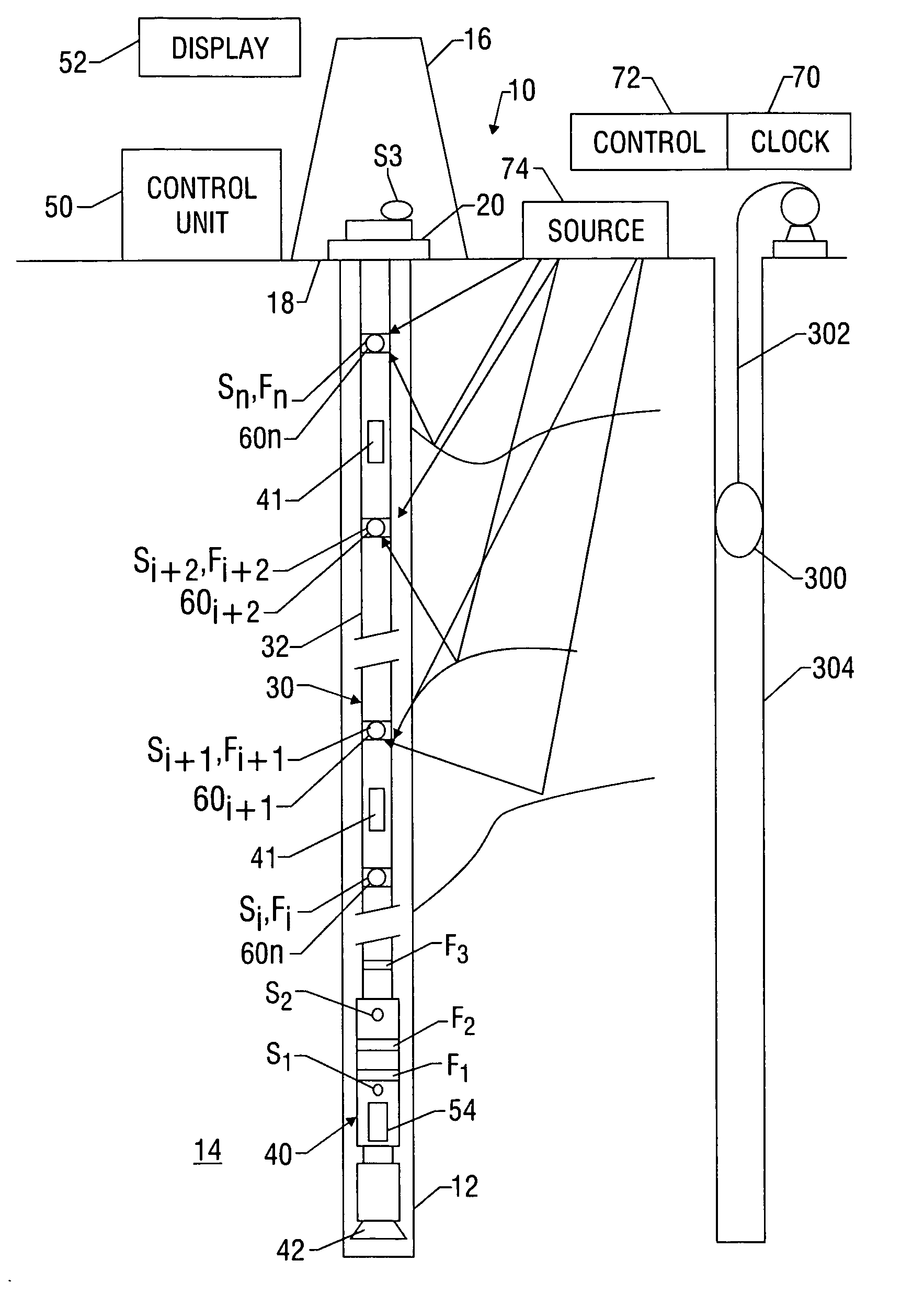
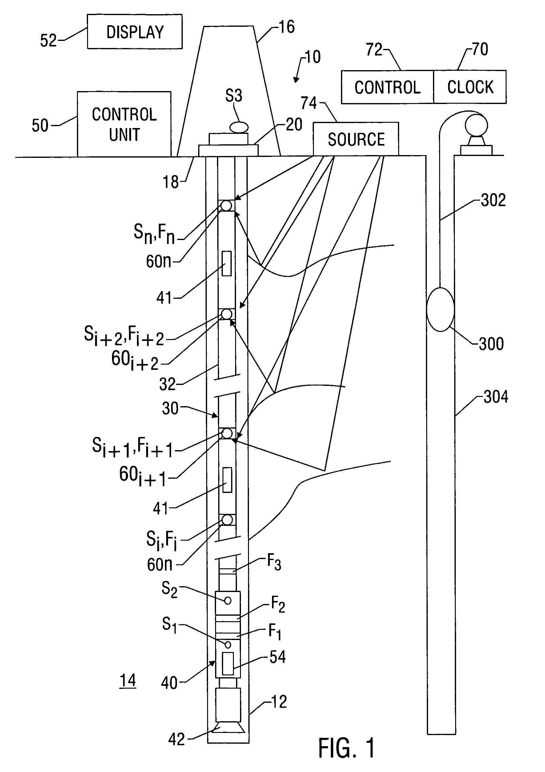
[0028]Referring initially to FIG. 1, there is schematically illustrated a drilling system 10, which can be land-based or offshore, made according to one embodiment of the present invention for forming a wellbore 12 in a subterranean formation 14. The drilling system 10 includes a derrick 16 erected on a floor 18 that supports a rotary table 20 that is rotated by a prime mover. The system also includes a drill string 30 having a plurality of jointed tubulars 32 and a drilling assembly 40 coupled at an end thereof. The drilling assembly 40 is also referred to as a bottom hole assembly (BHA) 40. A control unit 50 controls drilling operations and a display device 52 provides the operator or driller information relating to drilling in pictorial, numeric, and alphanumeric formats. Other related components and equipment of the system 10 are well known in the art and is not described in detail herein. Also, it should be understood that applications other than rotary drives (e.g., coiled tub...


PUM


Abstract

A drilling system includes a control unit and a bottomhole assembly (BHA) coupled to a drill string. The control unit uses measurements from sensors distributed throughout the drill string and BHA to determine the physical condition of the drill string and BHA and to determine whether drilling can be optimized. The drill string sensors are housed in receiver subs and optionally can be positioned on extensible members. The receiver sub also can include a short-hop telemetry module, a processor module, and a clock module. In one embodiment, the receiver subs include seismic sensors for enabling vertical seismic profiling. During operation, the processor visually presents to the operator via one or more graphical user interfaces a dynamically updated pictorial image representing the drilling system. The image is annotated with an appropriate visual signal to indicate a determined physical condition at a given location or component. The processor can also display recommended adjustments to drilling parameters for increasing drilling rates, improving tool life, and more precise steering.

Description

CROSS-REFERENCE TO RELATED APPLICATIONS[0001]None.FIELD OF THE INVENTION[0002]This invention relates generally to oilfield wellbore drilling systems that utilize distributed measurements to optimize drilling. In another aspect, this invention relates to control devices that provide a pictorial display of the drilling system to convey information regarding the physical health of the system.BACKGROUND OF THE ART[0003]To obtain hydrocarbons such as oil and gas, boreholes are drilled by rotating a drill bit attached at a drill string end. A large proportion of the current drilling activity involves directional drilling, i.e., drilling deviated and horizontal boreholes, to increase the hydrocarbon production and / or to withdraw additional hydrocarbons from the earth's formations. Modern directional drilling systems generally employ a drill string having a bottomhole assembly (BHA) and a drill bit at end thereof that is rotated by a drill motor (mud motor) and / or the drill string. A steeri...

Claims


Application Information

Patent Timeline
Patent Type & Authority Patents(United States)
IPC IPC(8): E21B47/00E21B47/12E21B49/00G01V1/42
CPCE21B47/12G01V1/42E21B49/00G01V1/34E21B44/00
Inventor BALLANTYNE, RAYMATHISZIK, HOLGERNEUBERT, MICHAEL
Owner BAKER HUGHES INC
Why Eureka
Try Eureka