Active/passive seal rotating control head

a rotating control head and passive sealing technology, applied in the direction of drilling pipes, drilling casings, borehole/well accessories, etc., can solve the problems of hazard to the drilling crew and equipment, prone to maintenance of rotating equipment, and large expenditure of manpower and equipment for hydrocarbon drilling

Inactive Publication Date: 2006-05-09
WEATHERFORD TECH HLDG LLC
View PDF20 Cites 92 Cited by
  • Summary
  • Abstract
  • Description
  • Claims
  • Application Information

AI Technical Summary

Benefits of technology

[0011]The present invention generally relates to an apparatus and method for sealing a tubular string. In one aspect, a drilling system is provided. The drilling system includes a rotating control head for sealing the tubular string while permitting axial movement of the string relative to the rotating control head. The drilling system also includes an actuating fluid for actuating the rotating control head and maintaining a pressure differential between a fluid pressure in the rotating control head and a wellbore pressure. Additionally, the drilling system includes a cooling medium for passing through the rotating control head.
[0012]In another aspect, a rotating control head is provided. The rotating control head includes a sealing member for sealing a tubular string while permitting axial movement of the string relative to the rotating control head. The rotating control head further includes an actuating fluid for actuating the rotating control head and maintaining a pressure differential between a fluid pressure in the rotating control head and a wellbore pressure.
[0013]In another aspect, a method for sealing a tubular in a rotating control head is provided. The method includes supplying fluid to the rotating control head and activating a seal arrangement to seal around the tubular. The method further includes passing a cooling medium through the rotating control head and maintaining a pressure differential between a fluid pressure in the rotating control head and a wellbore pressure.

Problems solved by technology

Drilling a wellbore for hydrocarbons requires significant expenditures of manpower and equipment.
Rotating equipment is particularly prone to maintenance as the drilling environment produces abrasive cuttings detrimental to the longevity of rotating seals, bearings, and packing elements.
In many instances, the formations produce gas or fluid pressure that may be a hazard to the drilling crew and equipment unless properly controlled.
However, the hydraulic circuit in the conventional active seal rotating control head has a less than desirable response time to rapidly changing wellbore pressure.
The axial movement of the drill pipe causes wear and tear on the bearing and seal assembly and subsequently requires repair.
The process is time consuming and can be dangerous.
Additionally, the thrust generated by the wellbore fluid pressure and the radial forces on the bearing assembly causes a substantial amount of heat to build in the conventional rotating control head.
The heat causes the seals and bearings to wear and subsequently require repair.
However, the oil based cooling system may be very expensive to implement and maintain.

Method used


Image

  • Active/passive seal rotating control head
  • Active/passive seal rotating control head
  • Active/passive seal rotating control head

Examples


Embodiment Construction

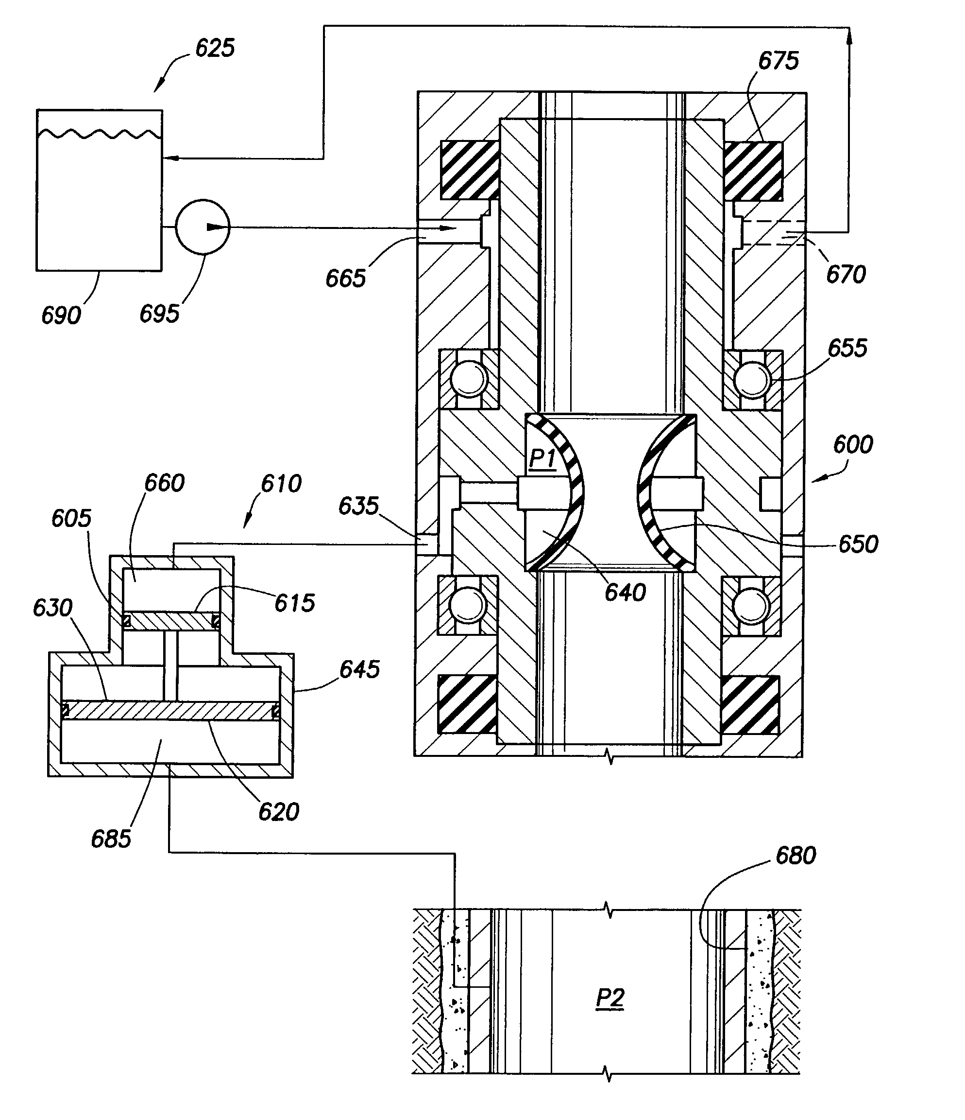
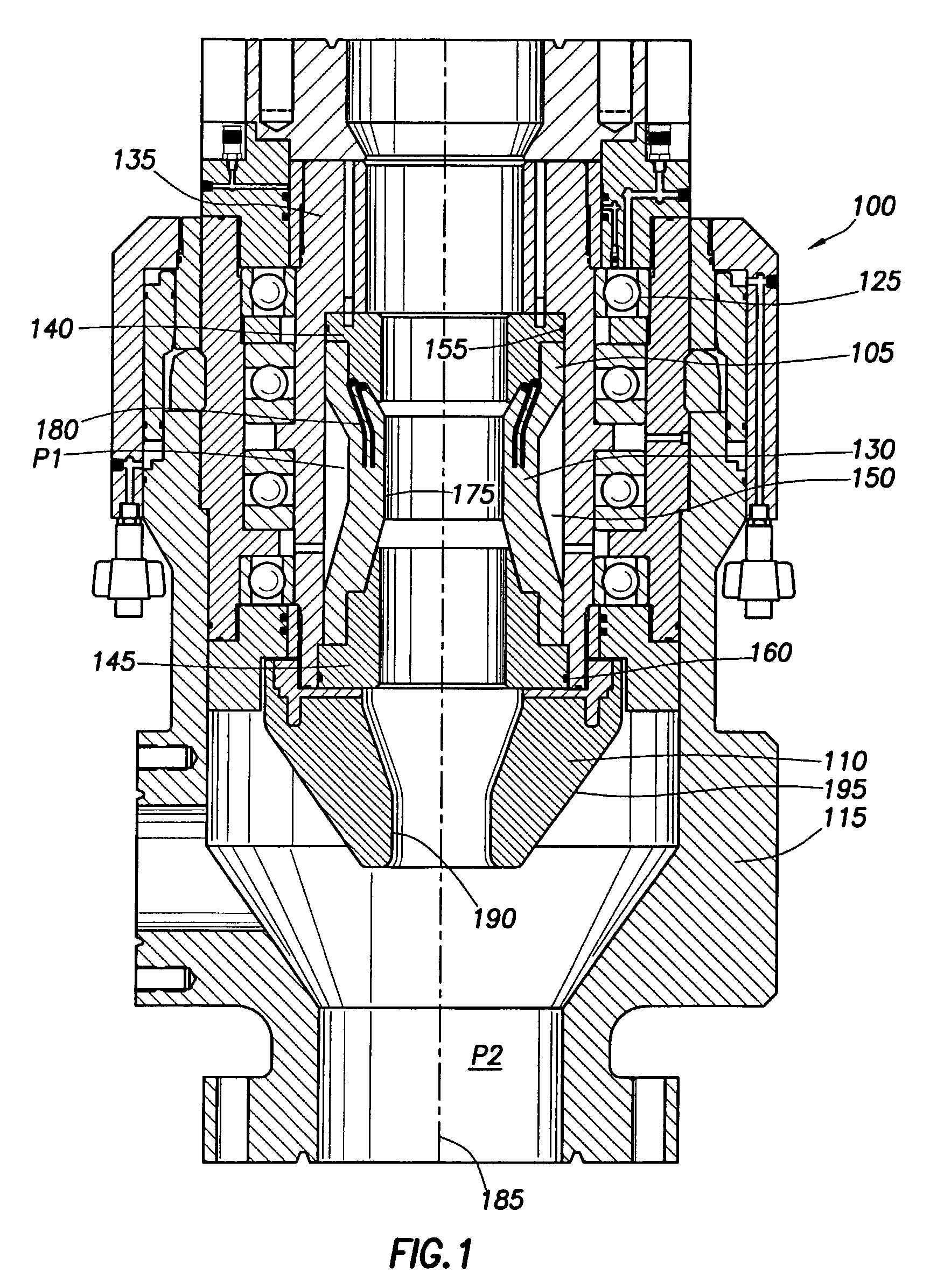
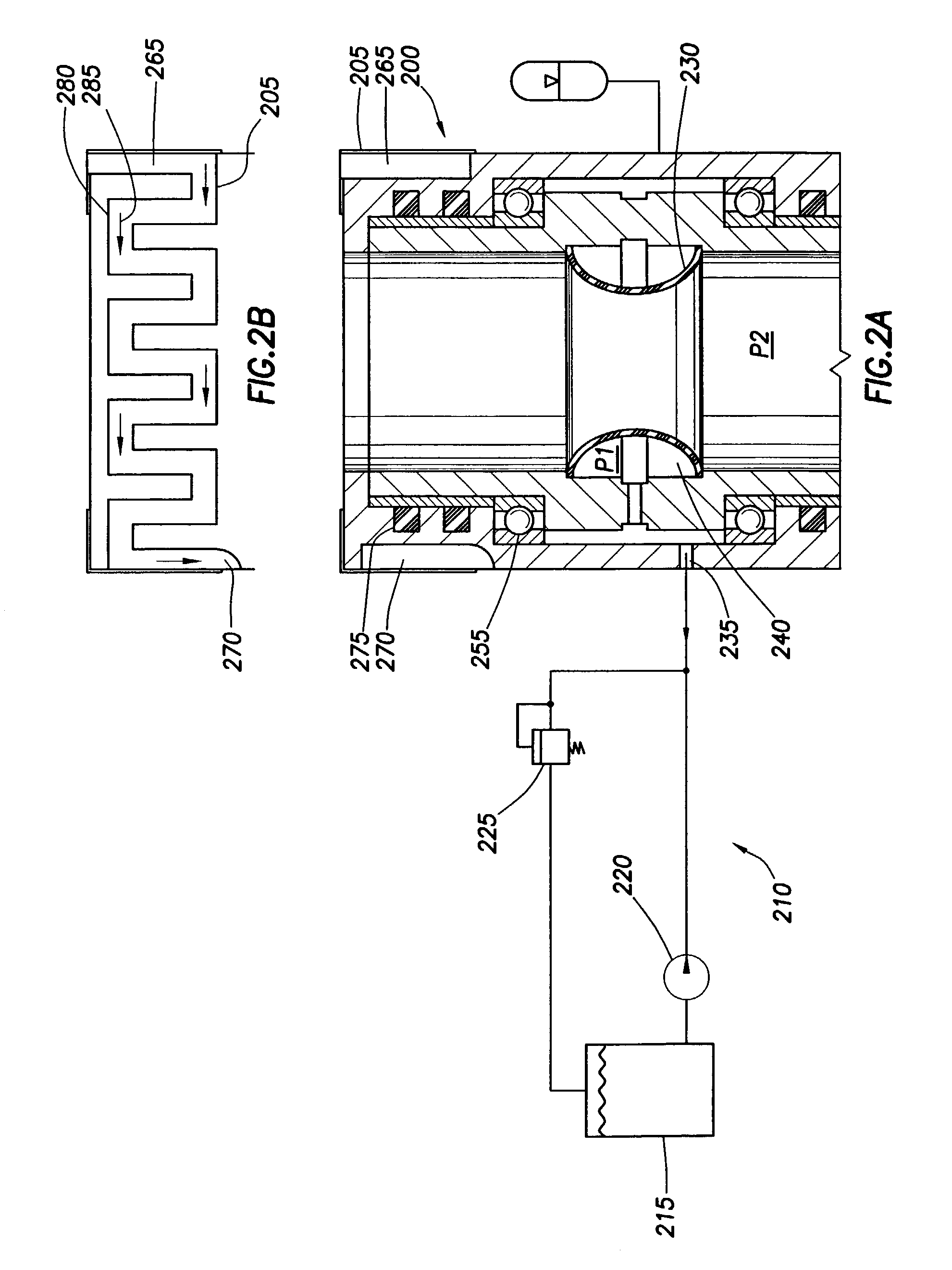
[0028]Generally, the present invention relates to a rotating control head for use with a drilling rig. Typically, an internal portion of the rotating control head is designed to seal around a rotating tubular string and rotate with the tubular string by use of an internal sealing element, and rotating bearings. Additionally, the internal portion of the rotating control head permits the tubular string to move axially and slidably through the rotating control head on the drilling rig. FIG. 1 generally describes the rotating control head and FIGS. 2–6 illustrate various methods of cooling and actuating the rotating control head. Additionally, FIGS. 7 and 8 illustrate alternate embodiments of the rotating control head.

[0029]FIG. 1 is a cross-sectional view illustrating the rotating control head 100 in accord with the present invention. The rotating control head 100 preferably includes an active seal assembly 105 and a passive seal assembly 110. Each seal assembly 105, 110 includes compo...


PUM


Abstract

The present invention generally relates to an apparatus and method for sealing a tubular string. In one aspect, a drilling system is provided. The drilling system includes a rotating control head for sealing the tubular string while permitting axial movement of the string relative to the rotating control head. The drilling system also includes an actuating fluid for actuating the rotating control head and maintaining a pressure differential between a fluid pressure in the rotating control head and a wellbore pressure. Additionally, the drilling system includes a cooling medium for passing through the rotating control head. In another aspect, a rotating control head is provided. In yet another aspect, a method for sealing a tubular in a rotating control head is provided.

Description

BACKGROUND OF THE INVENTION[0001]1. Field of the Invention[0002]Embodiments of the present invention relate generally to a method and an apparatus for a drilling operation. More particularly, the invention relates to a rotating control head. Still more particularly, the invention relates to the actuation and cooling of a rotating control head.[0003]2. Description of the Related Art[0004]Drilling a wellbore for hydrocarbons requires significant expenditures of manpower and equipment. Thus, constant advances are being sought to reduce any downtime of equipment and expedite any repairs that become necessary. Rotating equipment is particularly prone to maintenance as the drilling environment produces abrasive cuttings detrimental to the longevity of rotating seals, bearings, and packing elements.[0005]In a typical drilling operation, a drill bit is attached to a drill pipe. Thereafter, a drive unit rotates the drill pipe through a drive member, referred to as a kelly as the drill pipe a...

Claims


Application Information

Patent Timeline
Patent Type & Authority Patents(United States)
IPC IPC(8): E21B33/068E21B33/08
CPCE21B33/085
Inventor BAILEY, THOMAS F.CHAMBERS, JAMESHANNEGAN, DON M.
Owner WEATHERFORD TECH HLDG LLC
Why Eureka
Try Eureka