Card socket

a card socket and socket technology, applied in the direction of coupling device connection, engagement/disengagement of coupling parts, instruments, etc., can solve the problems of low strength of a complex housing, difficult to form such a housing of resin with a reduced thickness, complicated housing shape, etc., to and reduce the thickness of the card socket.

Active Publication Date: 2013-09-03
JAPAN AVIATION ELECTRONICS IND LTD
View PDF23 Cites 7 Cited by
  • Summary
  • Abstract
  • Description
  • Claims
  • Application Information

AI Technical Summary

Benefits of technology

[0012]According to the present invention, since the contact is held on the housing, which bridges between the first part and the second part of the base frame, the thickness of the card socket can be reduced with a simple structure.
[0013]Additionally, according to the present invention, there is no positional limitations that have been imposed on holding portions for holding the contacts of Patent Literature 2. In the card socket of Patent Literature 2, contact portions of the contacts are arranged between held portions and a rear end of the card socket in an insertion direction of a card. The contacts (the contact portions in particular) need to be formed and arranged so as not to interfere with an inserted card when the card is inserted from the rear end toward a front end of the card socket. Specifically, tip portions of the contacts should be bent downward so that the contacts can guide the inserted card smoothly. Without such a configuration, the contact portions of the contacts would be brought into contact with terminals of the card and would possibly be deformed. In such a case, there would be a restriction that a margin is required in the thickness direction. This restriction would limit reduction in thickness of the card socket. In contrast, such a restriction is eliminated if the contacts are arranged so that the contact portions of the contacts are located closer to the front end of the card socket than the held portions of the contacts are. Therefore, according to the present invention, further reduction in thickness can be achieved as compared to the card socket of Patent Literature 2. Moreover, since the base frame of the card socket according to the present invention has the connection portion, the strength is advantageously increased in the second direction as compared to the card socket of Patent Literature 2.
[0014]Furthermore, according to the present invention, the first switch piece, which constitutes the detection switch, is formed integrally with the cover. Therefore, even if a normally-closed type detection switch is used, deformation of components of the card socket (e.g., deformation of resin of the housing and positional deviation of the switch pieces caused by such deformation) can be reduced at the time when reflow mounting is carried out. The normally-closed type refers to a type in which the first switch piece and the second switch piece are in contact with each other before the card has been inserted. Particularly, when the backup part is provided on the metal member (e.g., the base frame of the present invention or a metal member separately incorporated in a housing of the prior art), which is combined with the cover, the risk of deformation of the components of the card socket can further be reduced at the time of the reflow mounting. In this case, a force applied to the second switch piece by contact of the first switch piece and the second switch piece is received via the switch piece holding housing in the first direction by the backup part.

Problems solved by technology

Therefore, the shape of the housing becomes complicated.
It is relatively difficult to form such a housing of resin with a reduced thickness.
Furthermore, there is a problem that the strength of a housing having a complicated structure becomes low if the thickness of the card socket is reduced.
Additionally, in the case of the card socket of Patent Literature 2, it is structurally difficult to provide a detection switch as illustrated in Patent Literature 3 without an increase of the size of the card socket.

Method used


Image

  • Card socket
  • Card socket
  • Card socket

Examples


Embodiment Construction

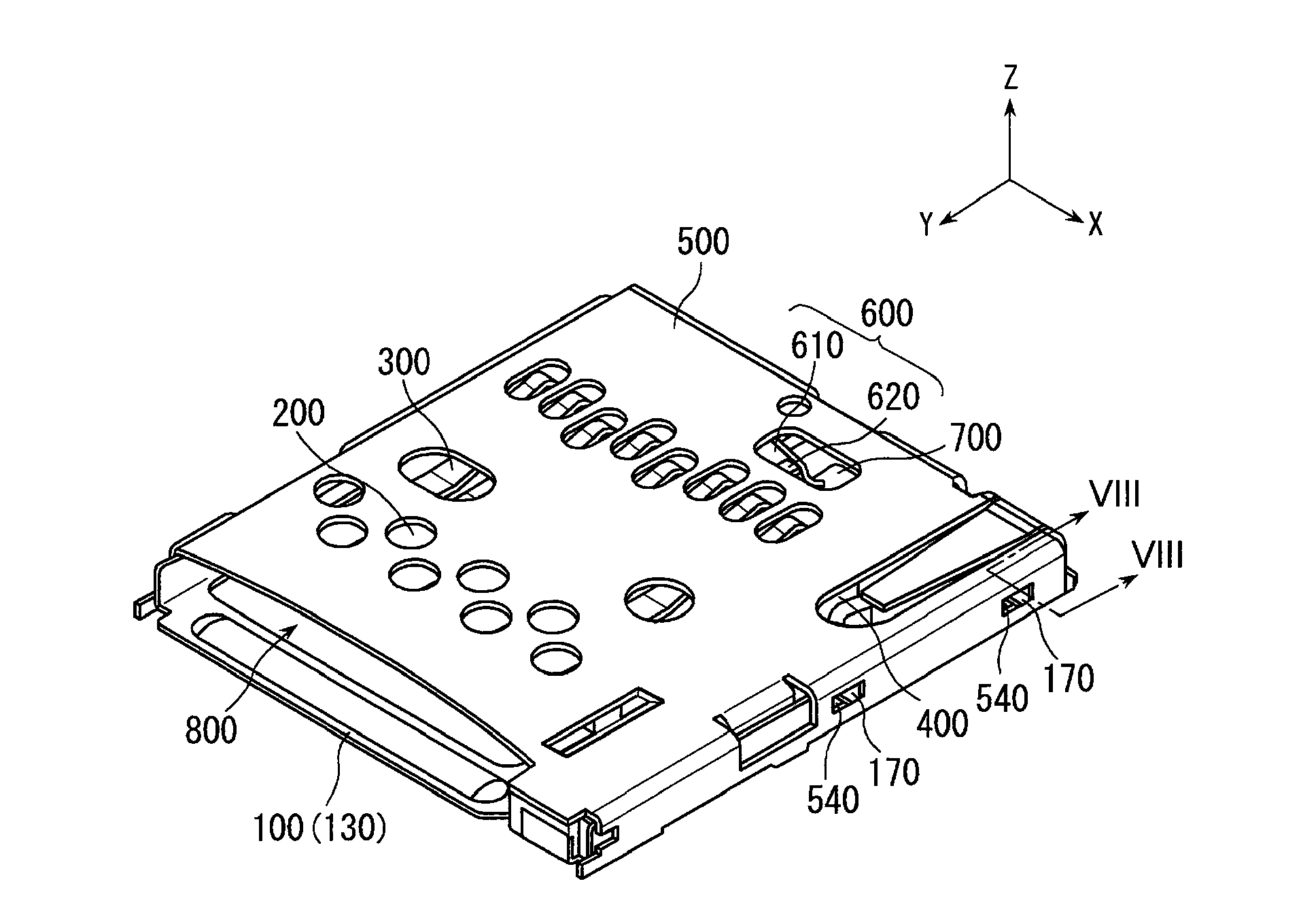
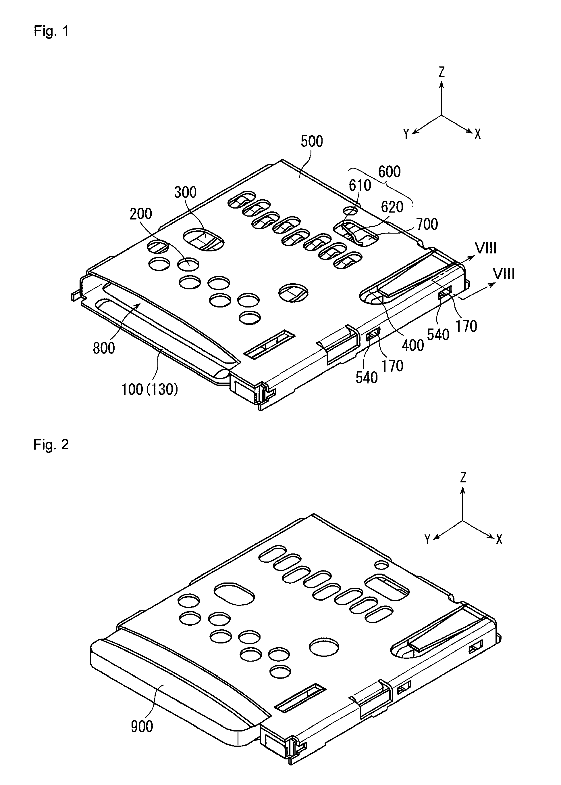
[0063]A card socket according to an embodiment of the present invention is a card socket for a MicroSD card and is of a so-called push-push type. Particularly, the present invention relates to a card socket mounted on a cellular phone or the like by reflow soldering.

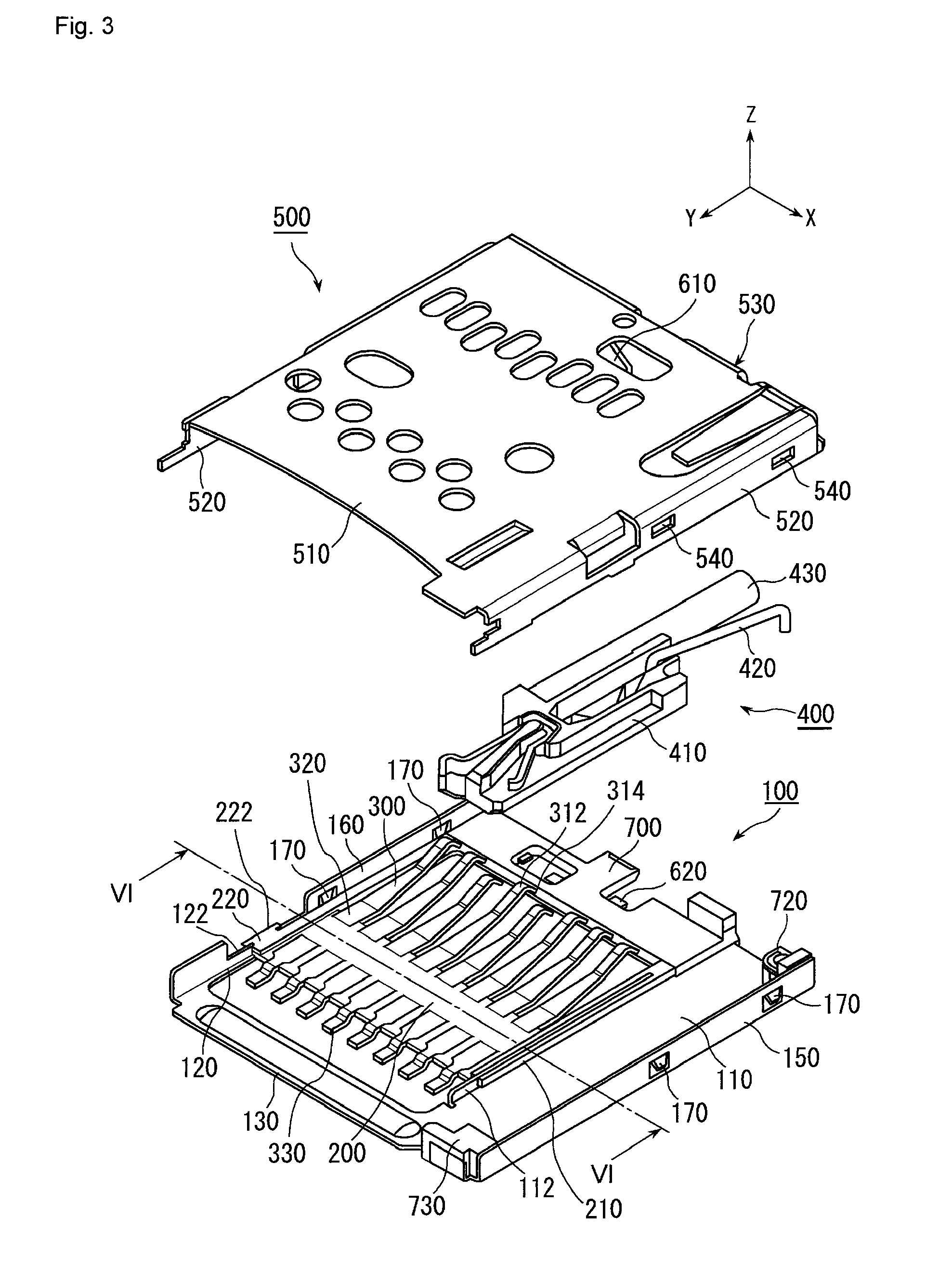
[0064]As shown in FIGS. 1 to 3, the card socket according to this embodiment has a base frame 100 made of metal, a housing 200 supported on the base frame 100, contacts 300 held on the housing 200, an ejection mechanism 400 configured to eject a card 900, a cover 500 made of metal, which covers the housing 200 and the contacts 300, a detection switch 600 configured to detect insertion of the card 900, and a switch piece holding housing 700 for holding part of the detection switch 600. The housing 200 and the switch piece holding housing 700 of this embodiment are made of resin.

[0065]As shown in FIGS. 3 and 4, the base frame 100 includes a first part 110, a second part 120, a first connection portion 130, a second connect...


PUM


Abstract

[Object] To provide a card socket having a structure that achieves a low profile.[Solving Means] The base portion of a card frame is basically constituted by a base frame (100) made of metal. Resin is used only for parts where absolutely necessary, such as a housing (200) for retaining contacts (300) and a switch piece holding housing (700) that retains a second switch piece (620). Thus, the resin thickness can be reduced while maintaining the strength of the card socket, so that the structure of the card socket is simplified and a low profile can be achieved.

Description

[0001]This application is a U.S. National Phase Application under 35 USC 371 of International Application PCT / JP2009 / 001404 filed Mar. 27, 2009.TECHNICAL FIELD[0002]The present invention relates to a card socket used for a small-sized electronic device, such as a cellular phone, and more particularly to a card socket for receiving at least part of a card such as a memory card.BACKGROUND ART[0003]For example, card sockets disclosed in Patent Literatures 1 to 3 have been known as this type of card sockets. Among others, the card socket disclosed in Patent Literature 2 has a structure capable of reducing the thickness of the card socket as compared to the card sockets of Patent Literatures 1 and 3.[0004]Generally, card sockets developed in recent years have a switch for detecting insertion and ejection of a card as with the card socket disclosed in Patent Literature 3.[0005]Patent Literature 1 JP-A 2005-228519[0006]Patent Literature 2 JP-A 2008-53124[0007]Patent Literature 3 JP-A 2007-...

Claims


Application Information

Patent Timeline
Patent Type & Authority Patents(United States)
IPC IPC(8): H01R24/00
CPCH01R12/716H01R2201/16G06K17/00H01R13/703
Inventor MATSUNAGA, AKIHIRO
Owner JAPAN AVIATION ELECTRONICS IND LTD
Why Eureka
Try Eureka