Vehicle electrical conduction path

a technology of electrical conduction path and vehicle, which is applied in the field of vehicle electrical conduction path, can solve the problems of inconvenient connection of parts to devices, power cables and control cables cannot be held in a desired wiring shape, and time-consuming and costly painting, etc., and achieves the effect of easy branching, convenient connection of power cables and convenient connection of control cables

Inactive Publication Date: 2013-09-03
HITACHI CABLE
View PDF19 Cites 31 Cited by
  • Summary
  • Abstract
  • Description
  • Claims
  • Application Information

AI Technical Summary

Benefits of technology

[0016]Accordingly, it is an object of the present invention to provide a vehicle electrical conduction path, which overcomes the above problems, and which allows the ease of production, and the ease of connection to a device.
[0043]According to the embodiments of the invention, since only the plural power cables are bundled with the braided shield, and the plural power cables bundled with the braided shield are arranged along the metallic pipe with the control cable accommodated therein, the power cables and the control cable are easily allowed to branch. Further, the branching portions of the power cables of the vehicle electrical conduction path are covered with the braided shield and therefore do not have to be provided with a separate shield. This allows the ease of connection of the power cables to devices. Also, in the vehicle electrical conduction path, the control cable extended out from the metallic pipe is allowed to be connected directly to the devices. This allows the ease of connection of the control cable to the devices.

Problems solved by technology

However, there arises the problem that this painting is very time-consuming and costly due to requiring heat resistance, and mechanical strength (adherence) causing no peeling during forming process, and also due to needing a good even coating in view of reliability thereof.
When the power cable or the control cable is accommodated in the corrugated tube, there arises the problem, however, that the power cable and the control cable cannot be held in a desired wiring shape due to the flexibility of the corrugated tube.
When the control cable with enhanced rigidity is accommodated in the corrugated tube as described above, there is therefore the problem that its portion to be connected to the device has to be very inconveniently reconnected to a flexible cable, and connected via the flexible cable to the device.

Method used


Image

  • Vehicle electrical conduction path
  • Vehicle electrical conduction path
  • Vehicle electrical conduction path

Examples


first embodiment

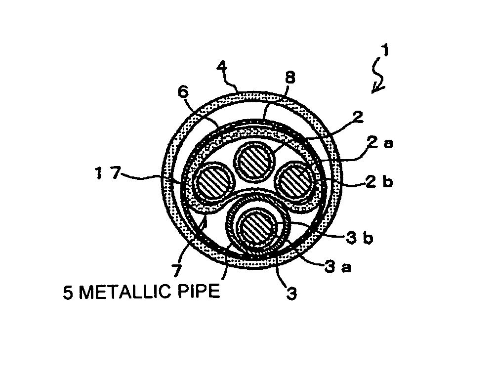
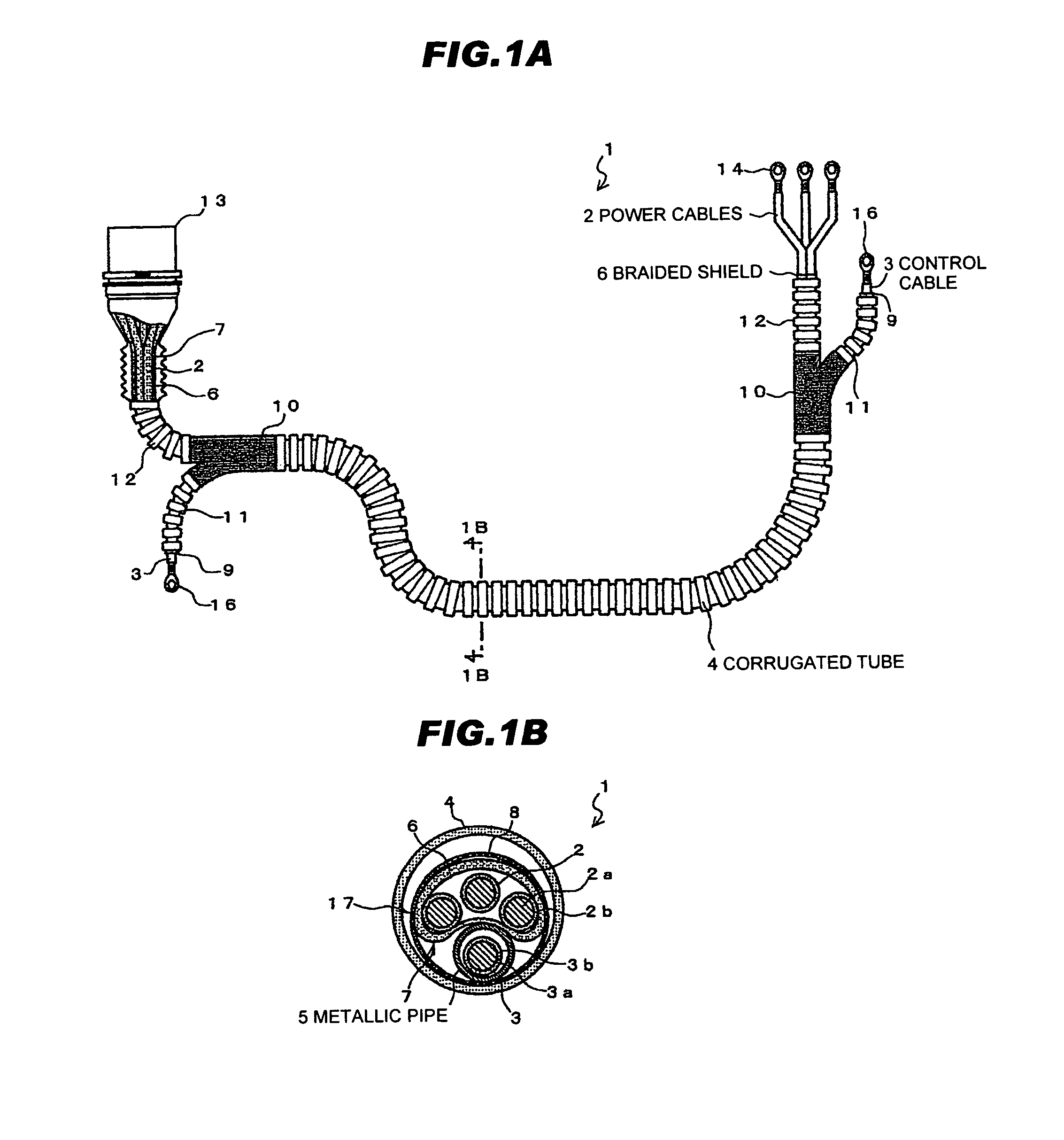
[0063]FIG. 1A is a plan view showing a vehicle electrical conduction path in a first preferred embodiment according to the invention, and FIG. 1B is a cross-sectional view taken along line 1B-1B in FIG. 1A.

[0064](Structure of a Vehicle Electrical Conduction Path 1)

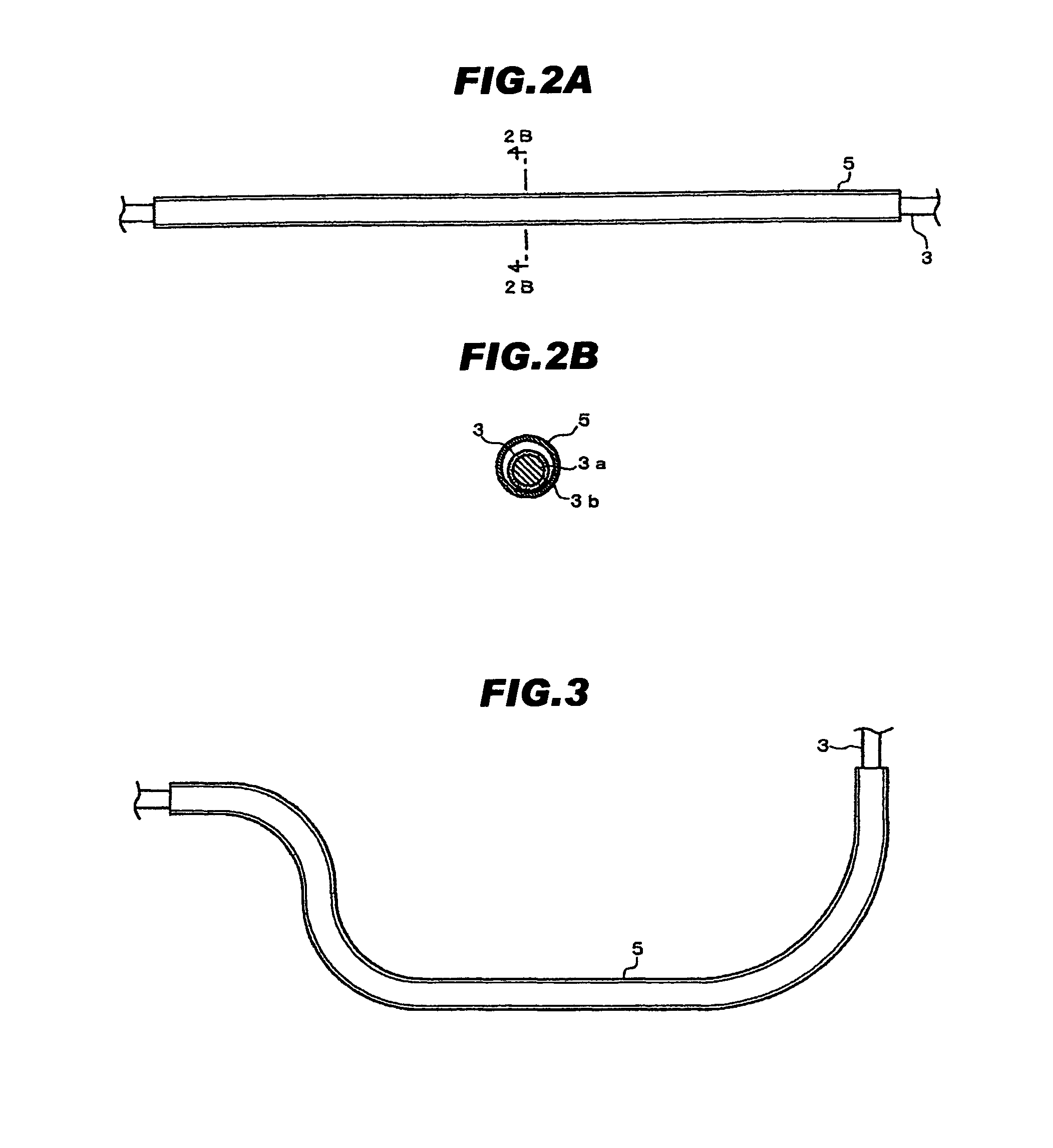
[0065]A vehicle electrical conduction path 1 in the first preferred embodiment according to the invention comprises a plurality of power cables 2, a braided shield 6 for bundling and shielding the plural power cables 2, at least one control cable 3, a metallic pipe 5 for being formable or moldable into a desired shape into which the control cable 3 is accommodated; and a corrugated tube 4 for serving as a flexible resin tube, wherein the plural power cables 2 bundled with the braided shield 6 are arranged along the metallic pipe 5, and a periphery thereof is covered with the corrugated tube 4.

[0066]In other words, the vehicle electrical conduction path 1 comprises the power cables 2, the braided shield 6 which bundles and ...

second embodiment

[0101]A second preferred embodiment according to the invention is described next.

[0102](Vehicle Electrical Conduction Path 91)

[0103]Referring to FIG. 9, a vehicle electrical conduction path 91 is basically configured as with the vehicle electrical conduction path 1 shown in FIGS. 1A and 1B, but the arrangement and shape of the power cables 2 (the shape of the power cable bundle 7) are different therefrom.

[0104]Although the vehicle electrical conduction path 1 shown in FIGS. 1A and 1B has the three power cables 2 arranged in a substantially C-shape in its cross-sectional view along a periphery of the metallic pipe 5, the vehicle electrical conduction path 91 of FIG. 9 has the power cable bundle 7 formed of the three power cables 2 bundled in a substantially triangular shape in its cross-sectional view, and arranged along one side of the metallic pipe 5. When the horizontal direction in FIG. 9 is the width direction of the vehicle electrical conduction path 91, and the vertical direct...

third embodiment

[0116]A third preferred embodiment according to the invention is described next.

[0117](Vehicle Electrical Conduction Path 111)

[0118]FIG. 11 is a cross-sectional view showing a vehicle electrical conduction path 111 in the third embodiment according to the invention.

[0119]The vehicle electrical conduction path 111 shown in FIG. 11 is basically configured as with the vehicle electrical conduction path 91 of FIG. 9, but differs therefrom in that an insulating layer 30 is provided between the metallic pipe 5 and the braided shield 6.

[0120]The insulating layer 30 in FIG. 11 is a sheath formed around the braided shield 6. In this embodiment, the insulating layer 30 is formed of a resin tube, and the power cable bundle 7 is inserted into this resin tube 30. This results in the insulating layer 30 formed around the braided shield 6. The insulating layer 30 is from 0.03 to 0.1 mm in thickness. The insulating layer 30 is preferred to be heat resistant and fire retardant, and may use a resin s...


PUM

PropertyMeasurementUnit
thicknessaaaaaaaaaa
diameteraaaaaaaaaa
diameteraaaaaaaaaa

Abstract

A vehicle electrical conduction path includes plural power cables, a braided shield which bundles and shields the plural power cables, a control cable, a metallic pipe which accommodates the control cable separately from the plural power cables, and a flexible resin tube which covers a periphery of the metallic pipe and the plural power cables bundled with the braided shield and arranged along the metallic pipe.

Description

[0001]The present application is based on Japanese patent application No. 2009-293096 filed on Dec. 24, 2009 and Japanese patent application No. 2010-081884 filed on Mar. 31, 2010, the entire contents of which are incorporated herein by reference.BACKGROUND OF THE INVENTION[0002]1. Field of the Invention[0003]The present invention relates to a vehicle electrical conduction path for use in hybrid vehicles, electric vehicles and the like.[0004]2. Description of the Related Art[0005]Conventional vehicle electrical conduction paths for use in hybrid vehicles, electric vehicles and the like have been disclosed in JP-A-2004-171952 and JP-A-2007-87628.[0006]JP-A-2004-171952 discloses a vehicle electrical conduction path having a plurality of electric cables collectively accommodated in a metallic pipe. The vehicle electrical conduction path is required to be held in a desired wiring shape (layout), for example at a lower surface of a vehicle body, as well as having a shield means, in view ...

Claims


Application Information

Patent Timeline
Patent Type & Authority Patents(United States)
IPC IPC(8): H01B11/02C07C227/18C07C227/40C07C229/28
CPCB60R16/0215C07C227/04C07C227/40C07C2601/14C07C229/28
Inventor KATO, KOICHIMAEJO, HAJIMEHORIKOSHI, TOSHIYUKI
Owner HITACHI CABLE
Why Eureka
Try Eureka